Model 5328A
Operation
SECTION
Ill
OPERATION
3-1.
INTRODUCTION
3-2.
This section containsoperating information necessary to understand operation and control
of the instrument. A description of basic counter operation
is
provided, followed by a front panel
operation summary for the standard mainframe (Figure 3-8) and a separate operation summary
for each option (Figures 3-10 through 3-13). Rear panel controls and connectors aredescribed in
Figure 3-9. Detailed information is provided on the use of controls and indicators. Information
on how to make measurements in the various measurement modes
is
provided in Section IV.
3-3. BASIC COUNTER OPERATION
3-4. The operation of the frequency counter
is
best understood by describing how thecounter
performs a frequency measurement.
if
n
is
the number of cycles of a signai that occurs in a time
period t, the average frequency
f
of that signal over the time period t
is
given by
3-5.
Frequency
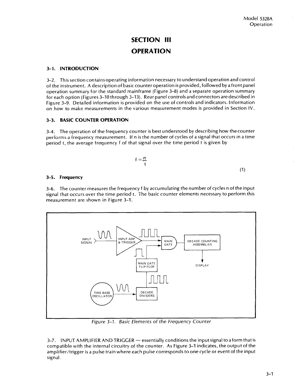
3-6.
The counter measures the frequency
f
by accumulating the number of cycles n of the input
signal that occurs over the time period t. The basic counter elements necessary to perform this
measurement are shown in Figure 3-1.
MAIN
GATE
FLIP FLOP
ASSEMBLIES
I
$.
DISPLAY
TIME BASE
DIVIDERS
I
Figure
3-7.
Basic Elements of the Frequency Counter
3-7. INPUT AMPLIFIER AND TRIGGER
-
essentially conditions the input signal to aform that
is
compatible with the internal circuitry of the counter. As Figure 3-1 indicates, the output of the
amplifier/trigger
is
a pulse train where each pulse corresponds to one cycle or event of the input
signal.
Artisan Technology Group - Quality Instrumentation ... Guaranteed | (888) 88-SOURCE | www.artisantg.com

 Loading...


