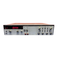
Model 5328A
Applications
4-20.
In T.I. A-B and T.I. AVG A-B with the rear panel ARM switch OFF, the counter
is
armed
-
by the run down of the SAMPLE RATE control. With the rear panel ARM switch ON,T.I. A-B and
T.I. AVG A--B are armed by an event at the C input (if Option 030 channel C
is
installed). For T.I.
AVG A+B, only one arming signal
is
required per average measurement (i.e., the counter doesn't
need to be armed prior to each individual time interval in the time interval measurement).
4-21.
TOTALIZING MEASUREMENTS
4-22. Two totalizing functions are available: START A and Events at C during the time interval
from A to B (Events C, A-B). In STARTA, the number of countsat theA input are totalized if N=l.
If N
is
greater than 1, A/N
is
totalized and the scaled output isavailableat the (TB OUT) rear panel
connector.
4-23. With Option 030 channel C, the events
C,
A-B function allows the number of events at
the
C
input to be totalized during a synchronized time interval defined by inputs to channels A
and B. A synchronized time interval means that the actual time interval during which events are
totalized
is
a multiple of 100 ns (or 10 ns with Option 040) and
is
synchronized to the counter's
,1,,1,
CIUCN.
4-24.
DVM MEASUREMENTS
4-25.
Option
020
4-26.
Three modes of Option 020 voltmeter operation may be selected: DVM, READ A, or
READ B. In the READ A and READ B modes, the digital voltmeter measures the trigger level of
channel A or B, regardless of the setting of the FUNCTION switch. To return control to the
FUNCTION control switch, the DVM control must beswitched back toDVM 100V RANGE. When
the digital voltmeter
is
in DVM 100V RANGE and the FUNCTION control
is
in DVM, the digital
voltmeter measures the external voltage applied to its input connector.
4-27.
The trigger level read by the voltmeter in READA or READ B modes must be multiplied by
the setting of the universal module's attenuator switch if using the standard universal module.
The trigger level represents the center of the hysteresis band. If using the Option 040 universal
module, the trigger level read by the DVM must be multiplied by 10
if
the universal module
attenuator position
is
in the X20 position (the X2 position
is
automatically accounted for)
if
the
FUNCTION control
is
in T.I. A--B or T.I. AVG A-B. The trigger level represents the top of the
hysteresis band for +slope and the bottom of the hysteresis band for -slope. In any other function,
the trigger level represents the middle of the hysteresis band.
4-28. The DVM'has a 0 to 125V range and allowable measurement times for
1
ms to 10
s.
These
times are determined by the setting of the RESOLUTION switch according to the following table.
Max. Sensitivity
100 mV
10 mV
1 mV
1 mV
I
mV
RESOLUTION, N Measurement Time
1 kHz 103 1 ms
.I
kHz 104 10 ms
10
HZ
105 100 ms
1 Hz 106
I
s
.I
HZ
10' 10
s
The Option 020 DVM issingle ended. Oneof the inputterminals isgrounded. Levels over125Vdc
are read as 125V dc. Maximum input
is
k500V dc.
4-29.
Option
021
4-30. Three modes of Option 021 voltmeter operation may be selected: DVM, READ A or READ
B. When a mode is selected (by depressing the appropriate pushbutton), the digital voltmeter
measures the trigger level of channel A or
B,
regardless of the setting of the FUNCTION switch. A
Artisan Technology Group - Quality Instrumentation ... Guaranteed | (888) 88-SOURCE | www.artisantg.com

 Loading...