Model 5328A
Applications
4-13.
TIME INTERVAL MEASUREMENTS
-
4-14.
One of two time interval functions can beselected, time interval or time interval average.
These functions measure the time interval between a START signal at the channel A input and
STOP signal at the channel
B
input. If both the START and the STOP signals are to be derived from
the same signal, place the universal module in COM A position. Separateslopeand level controls
for each channel allow variable triggering on either positive or negative going slope.
4-15.
In single shot time interval measurements, channel A opens the main gate and channel
B
closes the main gate. While the main gate
is
open, 10 MHz (100MHzforOption 040) isdivided by
the setting of the RESOLUTION switch and totalized by the counter. For optimum resolution,
select N=l. Other N values may be chosen to prevent display overflow (e.g., long time intervals)
or to get rid of
unstable digits. In time interval average measurements, the main gate
is
open for
the number of time intervals selected by the RESOLUTION switch. The standard 5328A 10 MHz
clock or the Option
040's 100MHz clock
is
totalized onlyduring the individual time intervals. The
resolution of the measurement
is
improved by the
fl.
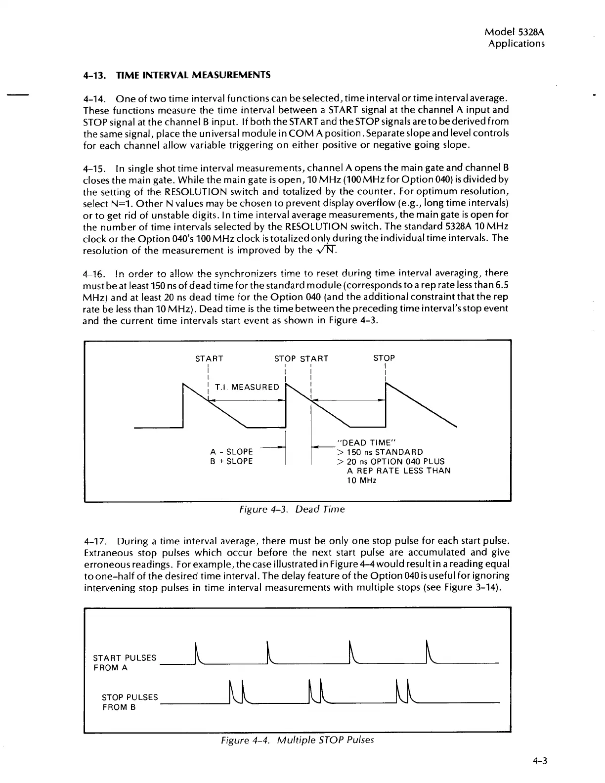
4-76.
!n
nrder
tc!
a!!nw
the
synchrnnizers
time to reset during time interval averaging, there
must be at least 150 ns of dead time for the standard module (corresponds to a rep rate less than 6.5
MHz) and at least 20 ns dead time for the Option 040 (and the additional constraint that the rep
rate be less than 10 MHz). Dead time
is
the time between the preceding time interval'sstop event
and the current time intervals start event as shown in ~i~urk 4-3.
-
I
START STOP S7
I
I
I
I
I
A
-
SLOPE
B
+
SLOPE
-i
\
RT STOP
I
-"DEAD TIME"
>
150
ns
STANDARD
>
20
ns
OPTION 040 PLUS
A REP RATE LESS THAN
10
MHz
I
Figure
4-3.
Dead Time
4-17.
During a time interval average, there must be only one stop pulse for each start pulse.
Extraneous stop pulses which occur before the next start pulse are accumulated and give
erroneous readings. For example, the case illustrated in Figure 4-4 would result in a reading equal
toone-half of the desired time interval. The delay feature of the Option 040
is
useful for ignoring
intervening stop pulses in time interval measurements with multiple stops (see Figure 3-14).
-
START PULSES
FROM A
STOP PULSES
FROM
B
Figure
4-4.
Multiple STOP Pulses
4-3
Artisan Technology Group - Quality Instrumentation ... Guaranteed | (888) 88-SOURCE | www.artisantg.com

 Loading...


