Model 5328A
Operation
3-70. The A and
B
input amplifiers have independent LEVEL, SLOPE, and ATTEN controls
regardless of the mode of operation (SEP or COM A).
3-71.
Signal Conditioning (Standard and Option
040)
3-72. AC-DC SWITCH. The AC-DC switch controls the coupling of the external signal to the
attenuator-amplifier by switching a capacitor in series in the AC position or by direct coupling in
the DC position. The obvious advantage of AC coupling
is
to provide a DC block for signals
containing a DC component. AC has the disadvantage of being unable to pass low frequency
signals (below 20
Hz
for the 5328A). A distinct advantage of having DC coupling cover the full
bandwidth (DC-100
MHz)
is
that extremely accurate time interval or pulse measurements can be
achieved even though pulse widths or repetition rates vary since the trigger point
is
independent
of the duty cycle of the input signal.
3-73. ATTENUATOR. The attenuator (ATTEN) connects the input signal directly to the amplifier
(in XI) or through a 10:l attenuator (X10) or a 100:l attenuator (X100) to increase thevoltage range
by 10or 100 times to allow measurement of high level signals that would otherwise be impossible
-.
without external attenuation.
I
he Option
040
ATTEN
is
Xi,
XZ,
or
XZO.
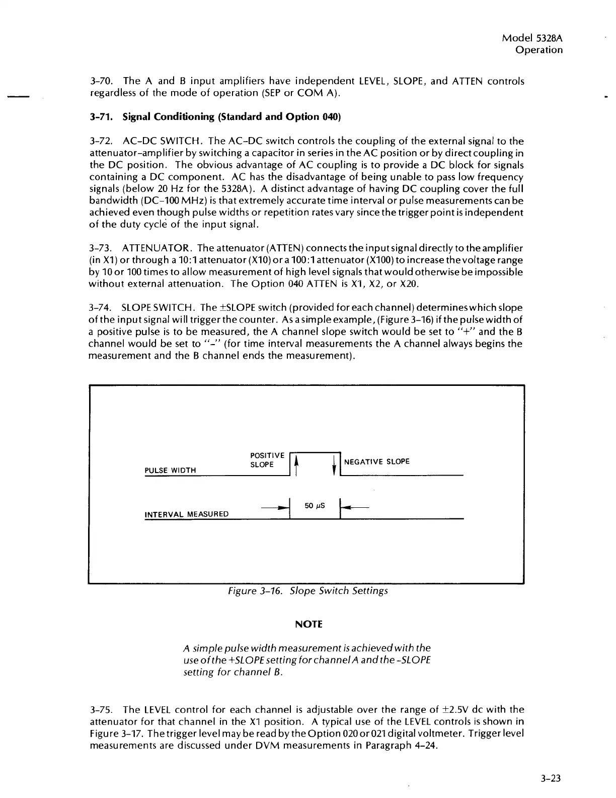
3-74. SLOPE SWITCH. The ?SLOPE switch (provided for each channel) determineswhich slope
of the input signal will trigger the counter. As asimple example, (Figure 3-16) if the pulse width of
a positive pulse
is
to be measured, the A channel slope switch would be set to
"+"
and the
B
channel would be set to
"-'I
(for time interval measurements the A channel always begins the
measurement and the
B
channel ends the measurement).
pOSITIVE
I
1
1
I
NEGATIVE SLOPE
SLOPE
PULSE WIDTH
50
!.IS
INTERVAL MEASURED
Figure
3-16.
Slope Switch Settings
NOTE
A simple pulse width measurement
is
achieved with the
use ofthe +SLOPE setting forchannelA and the -SLOPE
setting for channel
B.
3-75.
The LEVEL control for each channel
is
adjustable over the range of k2.5V dc with the
attenuator for that channel in the
XI
position.
A
typical use of the LEVEL controls
is
shown in
Figure 3-17. Thetrigger level may be read by theoption 020or021 digital voltmeter. Trigger level
measurements are discussed under DVM measurements in Paragraph 4-24.
Artisan Technology Group - Quality Instrumentation ... Guaranteed | (888) 88-SOURCE | www.artisantg.com

 Loading...


