Model 5328A
Operation
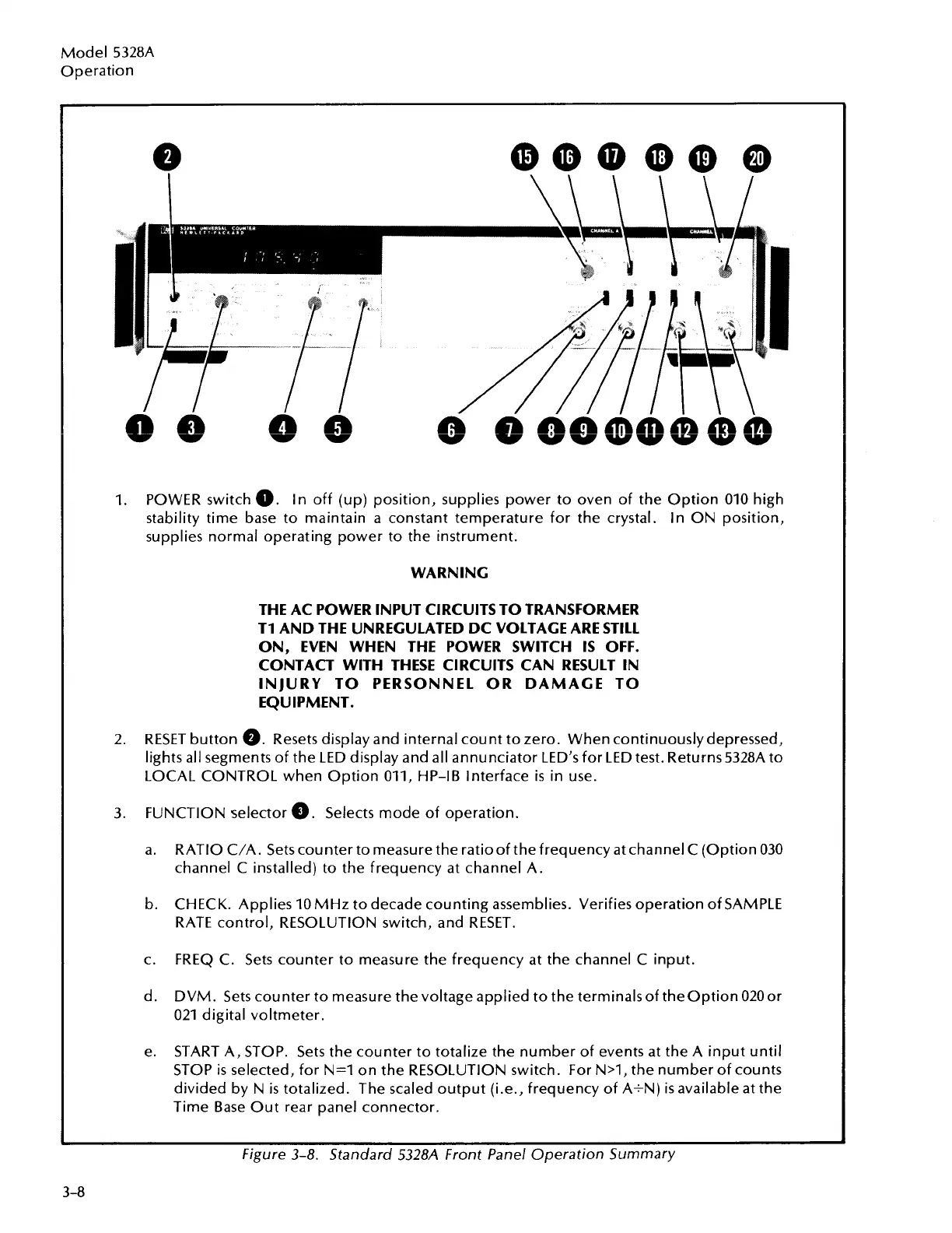
1.
POWER switch
0.
In off (up) position, supplies power to oven of the Option 010 high
stability time base to maintain a constant temperature for the crystal. In ON position,
supplies normal operating power to the instrument.
WARNING
THE AC POWER INPUT CIRCUITS TO TRANSFORMER
TI AND THE UNREGULATED DC VOLTAGE ARE STILL
ON,
EVEN WHEN THE POWER SWITCH IS OFF.
CONTACT WITH THESE CIRCUITS CAN RESULT
IN
INJURY TO PERSONNEL OR DAMAGE TO
EQUIPMENT.
2. RESET button
a.
Resets display and internal count to zero. When continuouslydepressed,
lights all segments of the LED display and all annunciator LED'S for LED test. Returns 5328A to
LOCAL CONTROL when Option 011, HP-IB Interface
is
in use.
3.
FUNCTION selector
a.
Selects mode of operation.
a. RATIO C/A. Sets counter to measure the ratioof the frequency at channel C (Option 030
channel
C
installed) to the frequency at channel A.
b. CHECK. Applies 10 MHz to decade counting assemblies. Verifies operation of SAMPLE
RATE control, RESOLUTION switch, and RESET.
c.
FREQ C. Sets counter to measure the frequency at the channel C input.
d.
DVM. Sets counter to measure the voltage applied to the terminalsof theoption 020or
021 digital voltmeter.
e. START A, STOP. Sets the counter to totalize the number of events at the A input until
STOP
is
selected, for N=l on the RESOLUTION switch. For N>1, the number of counts
divided by N
is
totalized. The scaled output (i.e., frequency of A+N)
is
available at the
Time Base Out rear panel connector.
Figure 3-8. Standard 5328A Front Panel Operation Summary
3-8
Artisan Technology Group - Quality Instrumentation ... Guaranteed | (888) 88-SOURCE | www.artisantg.com

 Loading...


