Model 5328A
Operation
3-30.
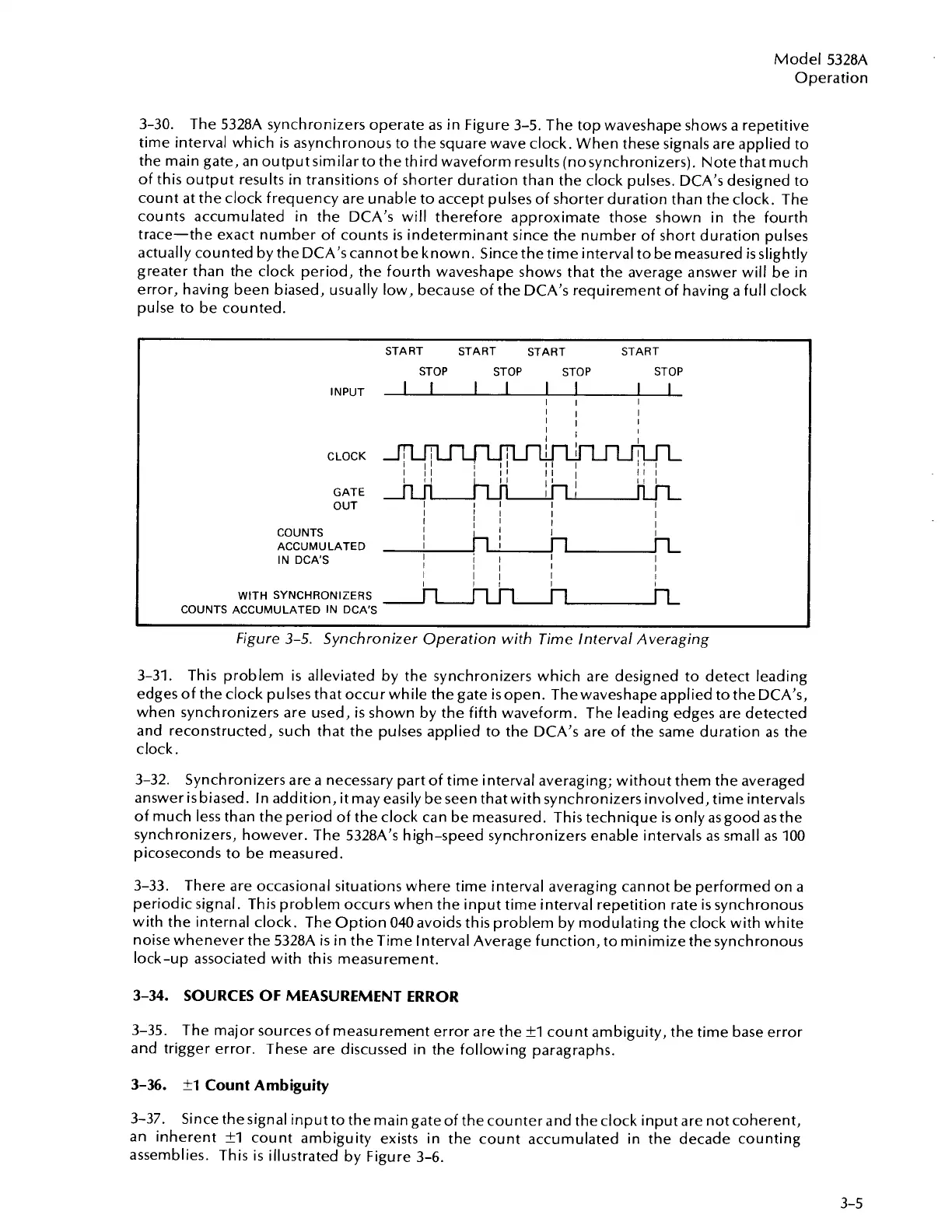
The 5328A synchronizers operate as in Figure 3-5. The top waveshape shows a repetitive
time interval which
is
asynchronous to the square wave clock. When these signals are applied to
the main gate, an output similar to the third waveform results (nosynchronizers). Note that much
of this output results in transitions of shorter duration than the clock pulses. DCA's designed to
count at the clock frequency are unable to accept pulses of shorter duration than the clock. The
counts accumulated in the DCA's will therefore approximate those shown in the fourth
trace-the exact number of counts
is
indeterminant since the number of short duration pulses
actually counted by the DCA's cannot be known. Since the time interval to be measured
is
slightly
greater than the clock period, the fourth waveshape shows that the average answer will be in
error, having been biased, usually low, because of the DCA's requirement of having a full clock
pulse to be counted.
START START
START
START
STOP
STOP
STOP
STOP
INPUT
I
1
1
I
I
1
I
1
I
I
I
I
I
I
I
I I
I
I
I
I
11
I
I
CLOCK
4
i
II
I
II
I
I
I
11
I
I !I
I
I1
11
I
I
i~
I!
I
GATE
OUT
I
I
I
I
I
I
I
I
I
1
!
I I
I
I
I
WITH
SYNCHRONIZERS
COUNTS
ACCUMULATED
IN DCA'S
I
COUNTS
I
I
I
I
ACCUMULATED
I
1
Figure
3-5.
Synchronizer Operation with Time Interval Averaging
IN
DCA'S
I
I
I I
I
I
I
I
I
3-31. This problem is alleviated by the synchronizers which are designed to detect leading
edges of the clock pulses that occur while the gate isopen. Thewaveshape applied to the DCA's,
when synchronizers are used,
is
shown by the fifth waveform. The leading edges are detected
and reconstructed, such that the pulses applied to the DCA's are of the same duration as the
clock.
I
I
I
3-32. Synchronizers are a necessary part of time interval averaging; without them the averaged
answer
is
biased. In addition, it may easily be seen thatwith synchronizers involved, time intervals
of much less than the period of the clock can be measured. This technique
is
only asgood as the
synchronizers, however. The 5328A's high-speed synchronizers enable intervals as small as 100
picoseconds to be measured.
3-33. There are occasional situations where time interval averaging cannot be performed on a
periodic signal. This problem occurs when the input time interval repetition rate
is
synchronous
with the internal clock. The Option 040 avoids this problem by modulating the clock with white
noise whenever the
5328A
is
in the Time Interval Average function, to minimize the synchronous
lock-up associated with this measurement.
3-34.
SOURCES OF MEASUREMENT ERROR
3-35. The major sources of measurement error are the
fl
count ambiguity, the time base error
and trigger error. These are discussed in the following paragraphs.
3-36.
tl
Count Ambiguity
3-37.
Since thesignal input to the main gateof the counter and the clock input are not coherent,
an inherent
?I
count ambiguity exists in the count accumulated in the decade counting
assemblies. This is illustrated by Figure 3-6.
Artisan Technology Group - Quality Instrumentation ... Guaranteed | (888) 88-SOURCE | www.artisantg.com

 Loading...


