Model 5328A
Applications
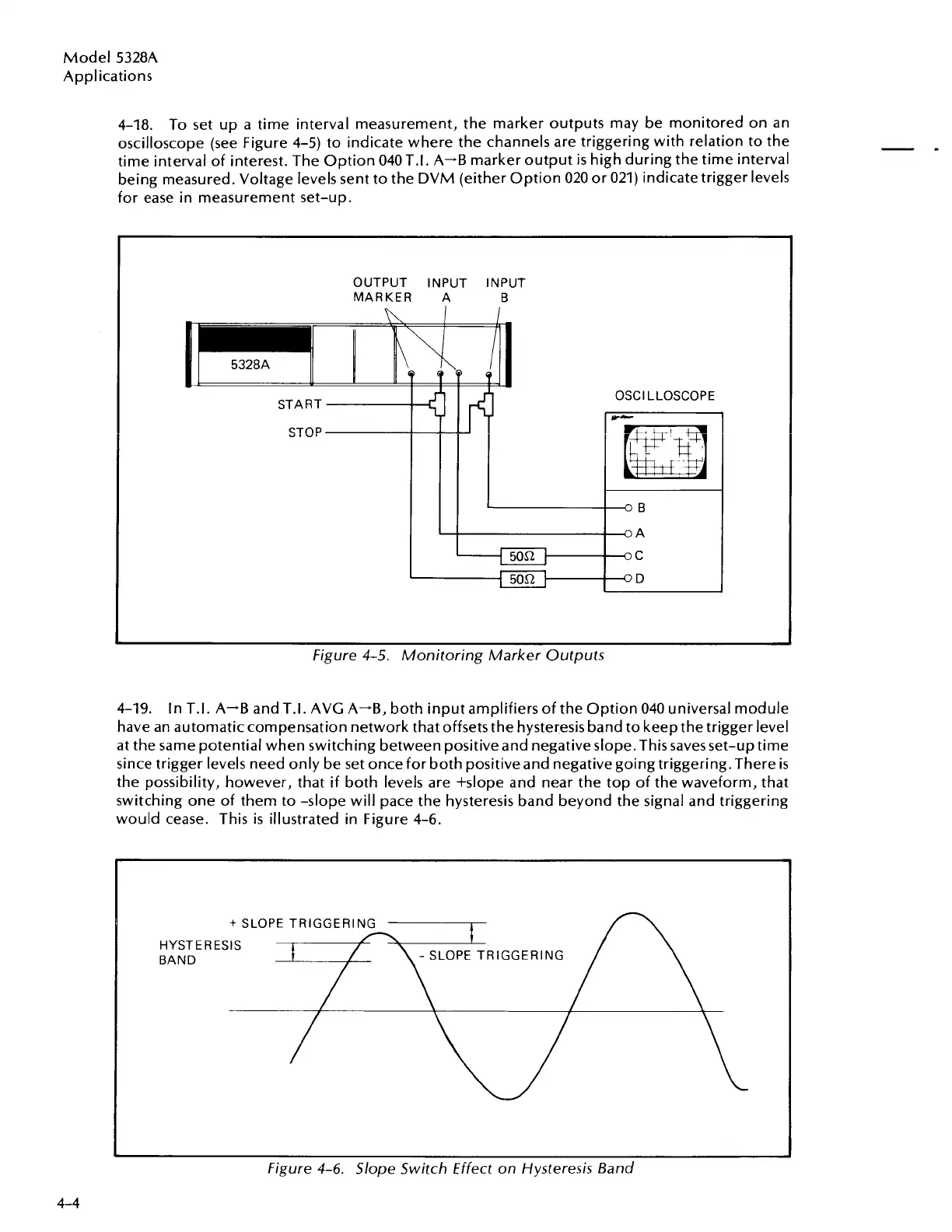
4-18. To set up a time interval measurement, the marker outputs may be monitored on an
oscilloscope (see Figure 4-5) to indicate where the channels are triggering with relation to the
time interval of interest. The Option 040T.I. A-B marker output
is
high during the time interval
being measured. Voltage levels sent to the DVM (either Option 020 or 021) indicate trigger levels
for ease in measurement set-up.
OUTPUT INPUT INPUT
MARKER
A
B
START
STOP
OSCl LLOSCOPE
w-
Figure 4-5. Monitoring Marker Outputs
4-19. In T.I. A-B and T.I. AVG A--B, both input amplifiers of the Option 040 universal module
have an automatic compensation network that offsets the hysteresis band to keep the trigger level
at the same potential when switching between positive and negative slope.This savesset-up time
since trigger levels need only be set once for both positiveand negative going triggering. There
is
the possibility, however, that if both levels are +slope and near the top of the waveform, that
switching one of them to -slope will pace the hysteresis band beyond the signal and triggering
would cease. This
is
illustrated in Figure 4-6.
HYSTERESIS
BAND
-
SLOPE TRIGGERING
-
Figure 4-6. Slope Switch Effect on Hysteresis Band
Artisan Technology Group - Quality Instrumentation ... Guaranteed | (888) 88-SOURCE | www.artisantg.com

 Loading...


