Model 5328A
Operation
3-16. Ratio
3-17.
By
replacing the time base with a second input of frequency,f2; the same configuration as
in Figure 3-2 can be used to measure the ratio f2/f. For higher resolution thesignal atfrequencyf
can be divided in decade steps in a manner identical to multiple period averaging.
3-18. Time Interval
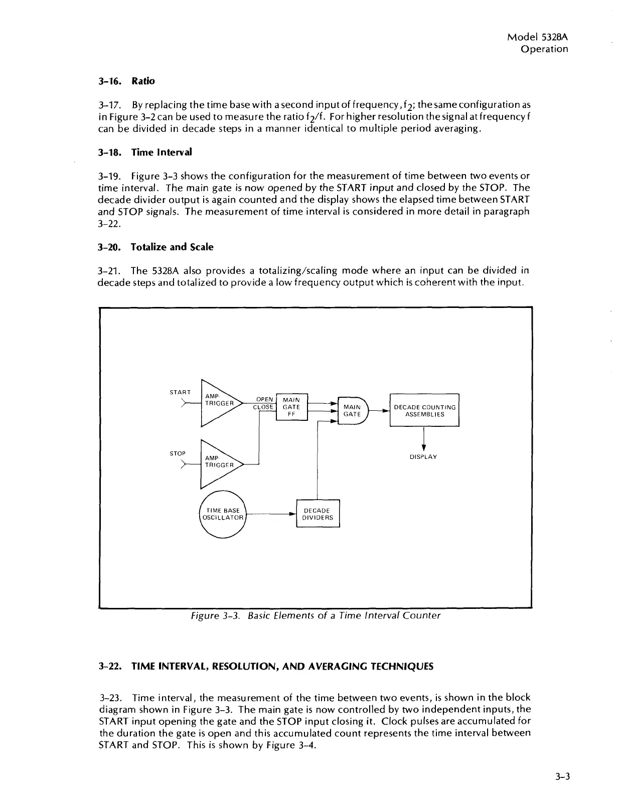
3-19.
Figure 3-3 shows the configuration for the measurement of time between two events or
time interval. The main gate
is
now opened by the START input and closed by the STOP. The
decade divider output is again counted and the display shows the elapsed time between START
and STOP signals. The measurement of time interval is considered in more detail in paragraph
3-22.
3-20. Totalize and Scale
3-21.
The 5328A also provides a totalizing/scaling mode where an input can be divided in
I
I
aecaae steps
and
totalized
to
provide
a
1o.i
freq~ency
output
which
is
coherent
with
the
-'r--
innl~t
START
nu
G
-'
MAIN
DECADE COUNTING
GATE ASSEMBLIES
I
STOP
>-
DISPLAY
DECADE
DIVIDERS
Figure
3-3.
Basic Elements of a Time Interval Counter
3-22.
TlME INTERVAL, RESOLUTION, AND AVERAGING TECHNIQUES
3-23. Time interval, the measurement of the time between two events,
is
shown in the block
diagram shown in Figure 3-3. The main gate is now controlled by two independent inputs, the
START input opening the gate and the STOP input closing it. Clock pulses are accumulated for
the duration the gate is open and this accumulated count represents the time interval between
START and STOP. This
is
shown by Figure 3-4.
Artisan Technology Group - Quality Instrumentation ... Guaranteed | (888) 88-SOURCE | www.artisantg.com

 Loading...


