Model 5328A
Operation
3-91.
When the OSC INT EXT switch
is
in the INT position, the 10 MHz oscillator output
is
available at the INT/EXT rear panel connector, providing TTL levels. When terminated in 50
ohms, the OSC INT EXT output
is
a square wave of approximately I-volt amplitude.
3-93.
Trigger Lights
3-94. A trigger light
is
providedfor each (A and B) input channels to enable the user to know not
only if the channel
is
triggering, but also in which direction the trigger level must be adjusted to
cause triggering. The light
is
ON when input
is
above the trigger level; OFF when input
is
below
the trigger level; BLINKING when channel
is
triggering. The trigger lights are operative over the
full frequency range of dc to 100 MHz.
3-95. The trigger lights can be used with a
10:l oscilloscope probe to providea logic probe type
function. By adjusting the trigger level to one tenth (since using
10:l divider probes) of the
threshold voltage for the logic family under investigation (e.g., .I4 volts for TTL), the light
indicates the logic state of circuit points which are contacted with the probe. When the trigger
level light
is
ON, the circuit node
is
a high (i.e., above the threshold voltage). If the light
is
OFF,
the
node
is
a
Ingical Inw.
!f
the light blinks, then pulses(upto100MHz rep rate) are presentatthe
node. The trigger lights can also detect the polarity of low rep rate pulses down to
5
nsec pulse
width. Positive pulses cause the light to blink on while negative pulsescause the light to blink off.
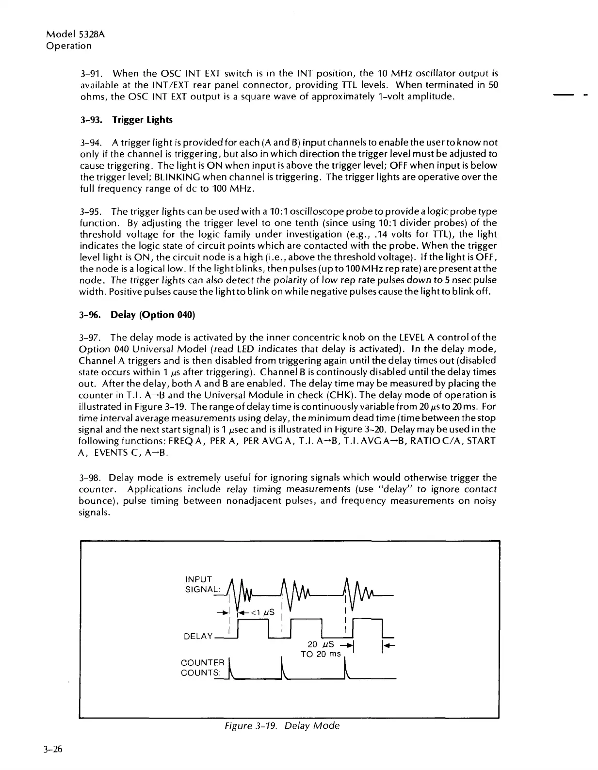
3-96.
Delay (Option
040)
3-97. The delay mode
is
activated by the inner concentric knob on the LEVEL A control of the
Option 040 Universal Model (read LED indicates that delay
is
activated).
In
the delay mode,
Channel A triggers and is then disabled from triggering again until the delay times out (disabled
state occurs within 1
ps
after triggering). Channel B
is
continously disabled until the delay times
out. After the delay, both A and B are enabled. The delay time may be measured by placing the
counter in T.I. A--B and the Universal Module in check (CHK). The delay mode of operation
is
illustrated in Figure 3-19. The rangeof delay time
iscontinuouslyvariablefrom
20psto 20ms. For
time interval average measurements using delay, the minimum dead time (time between thestop
signal and the next start signal)
is
1 psec and
is
illustrated in Figure 3-20. Delay may be used in the
following functions: FREQ A, PER A, PER AVC A, T.I. A-B, T.I. AVC A-B, RATIO C/A, START
A, EVENTS C, A-B.
3-98. Delay mode is extremely useful for ignoring signals which would otherwise trigger the
counter. Applications include relay timing measurements (use "delay" to ignore contact
bounce), pulse timing between nonadjacent pulses, and frequency measurements on noisy
signals.
I'
I
I
DELAY
I
I
I
Figure
3-79.
Delay Mode
3-26
-
--
20 PS
-q
It
TO
20
ms
COUNTER
COUNTS:
\
Artisan Technology Group - Quality Instrumentation ... Guaranteed | (888) 88-SOURCE | www.artisantg.com

 Loading...


