Model 5328A
Applications
/
ARM SWITCH ON
Figure 4-7. Measuring Linearity
SWEEP
GENERATOR
7
4-11. To make a PERIOD or PERIOD AVG measurement, select the desired function, select
appropriate input signal conditioning (see Paragraph 3-71), and apply the signal to theA input of
the standard or Option 040 universal module. For single period measurements, the
RESOLUTION switch scales the time base frequency which determines the resolution of the
measurement. For optimum resolution, select N=l. Other N values may bedesireable toprevent
display overflow or to get rid of unstable digits. For PERIOD AVG measurements, the
RESOLUTION switch selects the number of periods over which the period average measurement
is
made (the time base
is
10 MHz for this case). The PERIOD AVG mode gives increased resolution
and accuracy. Trigger error
is
decreased by N and the resolution
is
increased by N (resolution
=
100 ns or
?!?
for Option 040). The measurement time
is
equal to the period times N.
N N
SWEEP OUT
-
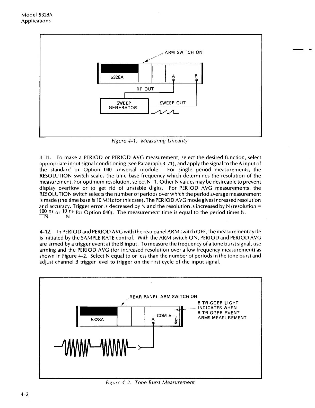
4-12.
In PERIOD and PERIOD AVG with the rear panel ARM switch OFF, the measurement cycle
is
initiated by the SAMPLE RATE control. With the ARM switch ON, PERIOD and PERIOD AVG
are armed by a trigger event at the
B
input. To measure the frequency of a tone burst signal, use
arming and the PERIOD AVG (for increased resolution over a low frequency measurement) as
shown in Figure 4-2. Select N equal to or less than the number of periods in the tone burst and
adjust channel
B
trigger level to trigger on the first cycle of the input signal.
J
REAR PANEL ARM SWITCH ON
B
TRIGGER LIGHT
INDICATES WHEN
r-COM A-7
B
TRIGGER EVENT
5328A A
8
ARMS MEASUREMENT
Figure 4-2. Tone Burst Measurement
Artisan Technology Group - Quality Instrumentation ... Guaranteed | (888) 88-SOURCE | www.artisantg.com

 Loading...


