2-8
Installing the HP 5400R zl2 Switches
Installation Procedures
Installing the HP 5400R zl2
Switches
1. Prepare the Installation Site
Cabling Infrastructure
Ensure the cabling infrastructure meets the necessary network specifications.
See Appendix B, “Cabling and Technology Information” on
page B-1 for more
information.
Installation Location
Before installing the switch, plan its location and orientation relative to other
devices and equipment:
■ In the front of the switch, allow at least 7.6 cm (3 inches) of space for the
twisted-pair and fiber-optic cabling.
■ In the back of the switch, allow at least 10.2 cm (4 inches) of space for the
power cord and cooling.
■ On the sides of the switch, leave at least 7.6 cm (3 inches) for cooling.
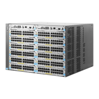
2. Install Switch Modules
Install switch modules into the slots as shown in the illustration below. For
installation details, see the instructions in the manual that comes with the
module.
Caution Make sure you install only HP Switch v2 zl or v3 zl2 Modules. HP Swtich vl zl
modules are not supported.
Avoid any electrostatic discharge problems by handling the modules only by
their bulkheads.
The slot cover can be removed, and the module can be installed with either a
flat-bladed or Torx T-10 screwdriver. Retain the slot cover for future use.
Module
Installation
Notes
■ Any of the supported Switch v2 zl or v3 zl2 Modules can be installed in
any of the slots.
 Loading...