Do you have a question about the HP ProCurve 1810G and is the answer not in the manual?
| Model | HP ProCurve 1810G |
|---|---|
| Layer | Layer 2 |
| Power Supply | Internal |
| VLAN Support | Yes, up to 256 VLANs |
| Ports | 8 or 24 10/100/1000 ports |
| Management | Web-managed |
| Switching Capacity | 16 Gbps (8-port), 48 Gbps (24-port) |
| Form Factor | Rack-mountable |
| Forwarding Rate | 11.9 Mpps (24-port model) |
| Jumbo Frame Support | Yes |
| Quality of Service (QoS) | Yes |
| Operating Temperature | 0°C to 40°C |
| Operating Humidity | 15% to 95% non-condensing |
Explains how to connect the switch to a network for remote management via a Web browser.
Describes accessing the switch's Web interface, including browser requirements and login procedures.
Details the steps to log into the switch's web interface, including browser compatibility.
Provides an overview of the switch's web interface layout and common elements.
Explains common elements found on configuration pages, like Help (?) and Apply buttons.
Describes how to save configuration changes to ensure they persist after a reboot.
Explains the Web Applet which shows a graphical representation of the switch and port status.
Describes the meaning of various LEDs on the switch, including Power, Fault, and Locator.
Explains the different LED modes (Act, FDx, Spd) and how they indicate port status.
Describes the left-port LED that indicates link status (On, Blinking, Off).
Displays software version, system uptime, name, location, and contact information.
Displays logged system messages, configuration failures, and user sessions.
Provides a summary and status of each port, including statistics on transmitted and received packets.
Displays summary and per-port information for LLDP frames transmitted and received.
Displays the configuration summary and status of each trunk.
Displays MAC addresses associated with incoming packets and their learned ports.
Shows whether Loop Protection is enabled or disabled on each port and its configuration.
Displays the status of the two system images (image1 and image2) on the switch.
Displays the current time, time zone, and Daylight Savings Time settings.
Configures network interface settings for connecting a management station to the switch.
Configures the switch to synchronize its clock with an SNTP server for accurate time.
Allows configuration of the local time zone for the switch.
Configures when Daylight Savings Time (DST) occurs for the switch's time zone.
Configures parameters for port operation, including physical type, link status, and admin mode.
Enables the switch to forward jumbo Ethernet frames, extending the standard MTU size.
Configures mirroring of packets sent/received on one port to another for analysis.
Enables flow control to prevent packet loss during network congestion by managing transmission rates.
Configures Green Mode, which turns off LEDs and reduces power consumption.
Provides automatic detection and handling of network loops to prevent performance degradation.
Configures Denial of Service (DoS) and Storm Control protections for enhanced network security.
Enables secure HTTPS management sessions using SSL for encrypted communication.
Instructions for downloading SSL certificates and DH encryption parameter files.
Procedures for the switch to generate its own self-signed public key certificates.
Creates and configures trunk interfaces, defining their properties like type and members.
Specifies which switch ports are included as members in each trunk.
Defines VLAN groups, assigning IDs and names to create distinct network segments.
Configures VLAN settings for individual ports, including PVID and port priority.
Defines how ports or trunks participate in VLANs and specifies the tagging policy for outgoing packets.
Provides a step-by-step example of creating a management VLAN to restrict user access.
Configures global LLDP parameters and protocol settings on individual ports.
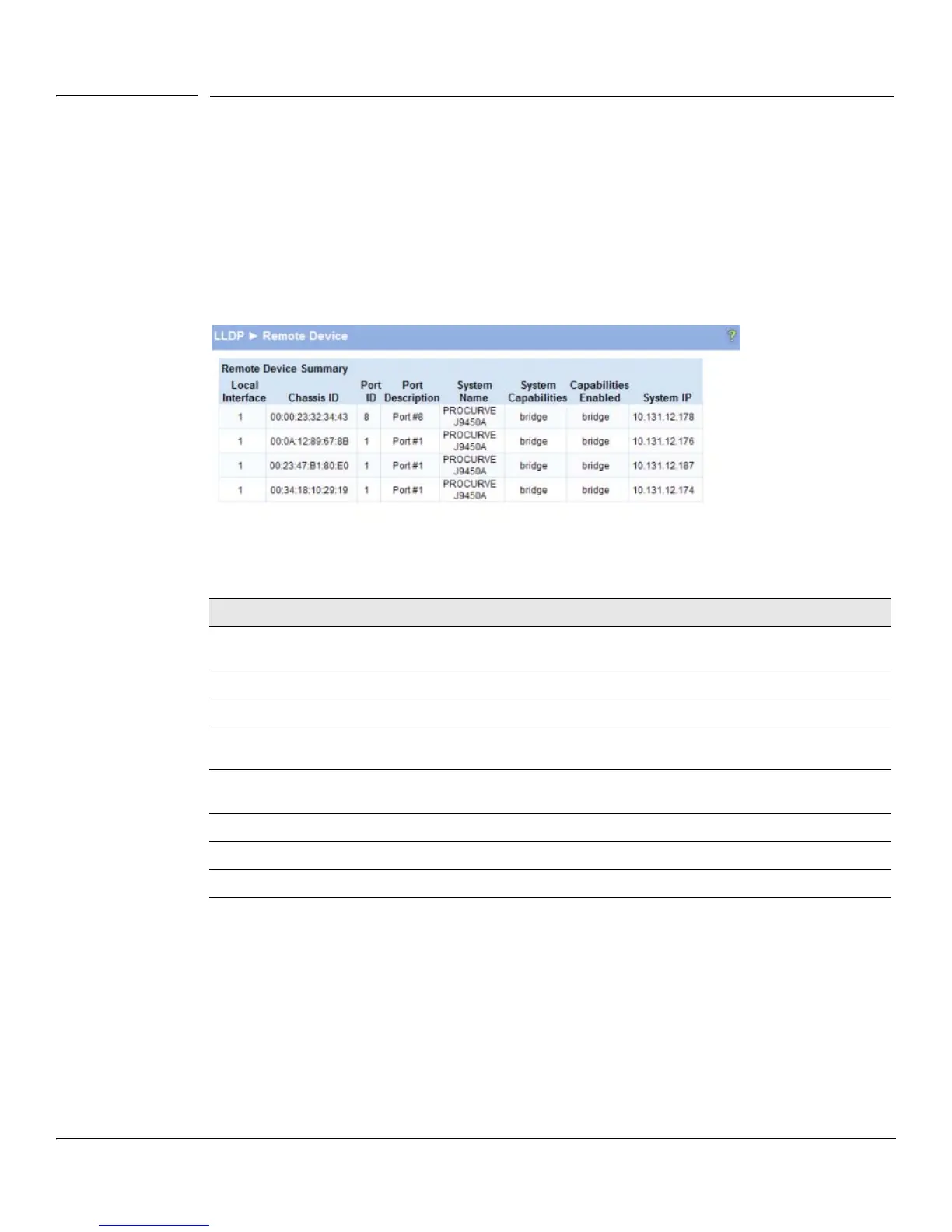
Displays information about devices on the network from which the switch has received LLDP information.
Displays information about remote devices for which the switch has received LLDP information.
Tests network reachability to other devices by sending ICMP echo requests.
Configures system message logging to the local log file or forwarding via Syslog protocol.
Allows performing a software reboot of the switch, with an option to save the current configuration.
Restores all switch settings to their factory default configuration.
Generates a summary of switch information for troubleshooting and support purposes.
Enables a locator LED on the switch to blink, aiding in physical device identification.
Saves a backup copy of the switch's image or configuration files to a local system or network directory.
Provides step-by-step instructions for backing up the switch's configuration file.
Uploads new software images or configuration files from a system or network to the switch.
Names and changes the next bootup image, allowing activation of stored images.
Changes the password used to access the switch's Web interface.
Saves any changes applied since the last reboot to the switch configuration file.