Step 7 Install the PCIe riser module.
For details, see 8.4.22 Installing a PCIe Riser Module.
Step 8 Install the server node.
For details, see 8.3.4 Installing an XH321 V5.
Step 9 Power on the server node.
For details, see 8.3.1 Power-On Procedure.
Step 10 Log in to the iBMC WebUI, and check whether the new component is normal.
For details, see
FusionServer Pro X6000 Server iBMC User Guide
.
Step 11 Install the driver for the PCIe card.
If the new PCIe card model is dierent from the old PCIe card model, install the new PCIe
card driver.
----End
8.4.21 Removing a PCIe Riser Module
Procedure
Step 1 Power
o the server node.
For details, see 8.3.2 Power-O Procedure.
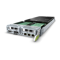
Step 2 Remove the server node.
For details, see 8.3.3 Removing an XH321 V5.
Step 3 Place the server node on the ESD workstation.
Step 4 Determine the position of the PCIe riser module.
Step 5 Remove the PCIe riser module.
1. Use a Phillips screwdriver to loosen the screws on the cover of the server
node. See (1) in Figure 8-58.
2. Remove the cover from the server node in the arrow direction. See (2) in
Figure 8-58.
3. Use a Phillips screwdriver to loosen the screw that secures the PCIe riser
module. See (3) in Figure 8-58.
4. Lift the PCIe riser module in the arrow direction. See (4) in Figure 8-58.
FusionServer Pro XH321 V5 Server Node
Maintenance and Service Guide 8 Parts Replacement
Issue 17 (2021-03-09) Copyright © Huawei Technologies Co., Ltd. 90
 Loading...
