CONNECTING VALVE WIRES
Connecting Station Valve Wires
Each station module that has been inserted has a grouping of six station
screw terminals corresponding to that particular expansion slot. Once a
station module is installed in a module slot, the station screw terminals
assigned to that module, which are located directly below the station
module, become active.
Each station output is rated for 0.56A max, or enough to operate two
Hunter AC solenoids simultaneously.
1. Route valve wires between control valve location and the controller.
2. At the valves, attach a common wire to either solenoid wire of all the
valves. This is most commonly a white colored wire. Attach a separate
control wire to the remaining wire of each valve. All valve wire splice
connections should be done using waterproof connectors.
3. Open the faceplate at the controller to expose the numbered station
terminals.
4. Route valve wires through the conduit and attach the conduit to the
controller at the 1 ½" (37.5 mm) opening at the bottom of the cabinet.
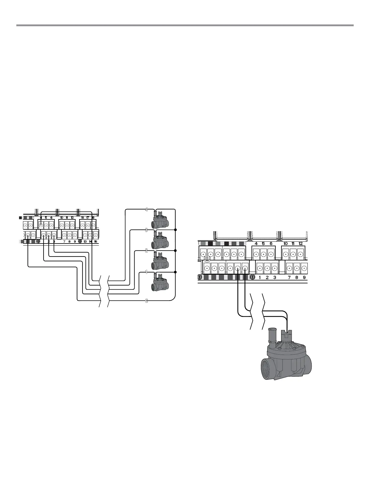
5. Strip ½" (13 mm) of insulation from the ends of all the wires. Secure
the valve common wire to one of three C (Common) terminals located
of the Power and Accessory terminals. All three common terminals are
active, so the valve common wire may be connected to either one.
Attach all the individual valve control wires to the appropriate station
terminals.
Valve Common Wire
Valve 1
Valve 2
Valve 3
Valve 4
Valve
Wires
Connecting a Master Valve or Pump Start Relay
Complete this section only if you have a Master Valve or Pump Start Relay
installed. The I-Core controller works with a normally closed master valve
that is typically installed at the supply point of the main line that opens only
when the automatic system is activated. A pump start relay is an electrical
device that uses the irrigation controller to activate a pump to provide
water to your system.
The Master Valve or Pump Start Relay connection is located on the
bottom row of the Power and Accessory Terminals, and is labeled P/MV.
This terminal will supply 24 VAC, 0.32A max, for a single Master Valve
solenoid. For a Pump Start Relay, the relay holding current draw must
not exceed 0.28 amps. If using a Pump Start Relay, it is recommended
that the controller be mounted at least 15' (4.5 m) away from both the
pump start relay and the pump. When a pump is to be operated by
the controller, a pump start relay must be used. Do not connect the
controller directly to the pump — damage to controller will result.
1. Route valve wires between Master Valve or Pump Start Relay location
and the controller.
2. At the Master Valve, attach a common wire to either solenoid wire of
the valve. Attach a separate control wire to the remaining solenoid
wire. At the Pump Start Relay, attach either wire to one of the yellow
wires coming from the Pump Start Relay. Attach the remaining wire to
the other yellow wire at the Relay. All wire splice connections should
be done using waterproof connectors.
3. Open the inner facepack door at the controller.
4. Route the valve wires into the controller via the eld
wire conduit.
5. Connect either wire from the Master Valve or Pump start Relay to the
P/MV terminal located on the bottom row of the Power and Accessory
terminals. Connect the remaining wire to the C (Common) terminal
that is located directly to the left of the P/MV terminal.
The Master Valve or Pump Start Relay can be activated according to a
particular station. The conguration of assigning the Master Valve or Pump
Start Relay according to a particular station will be covered in the Set Pump
Operation (pg. 18).
To P/MV or
Pump Start Relay
9
 Loading...