4
CONNECTING VALVES AND AC POWER ..............................................................................
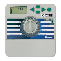
Transformer
Valve 1
Valve 2
Valve 3
Valve 4
alve Common Wire
alve
Wires
V
V
Yellow
Yellow
Green
AC2
AC1
GND
3 Wires
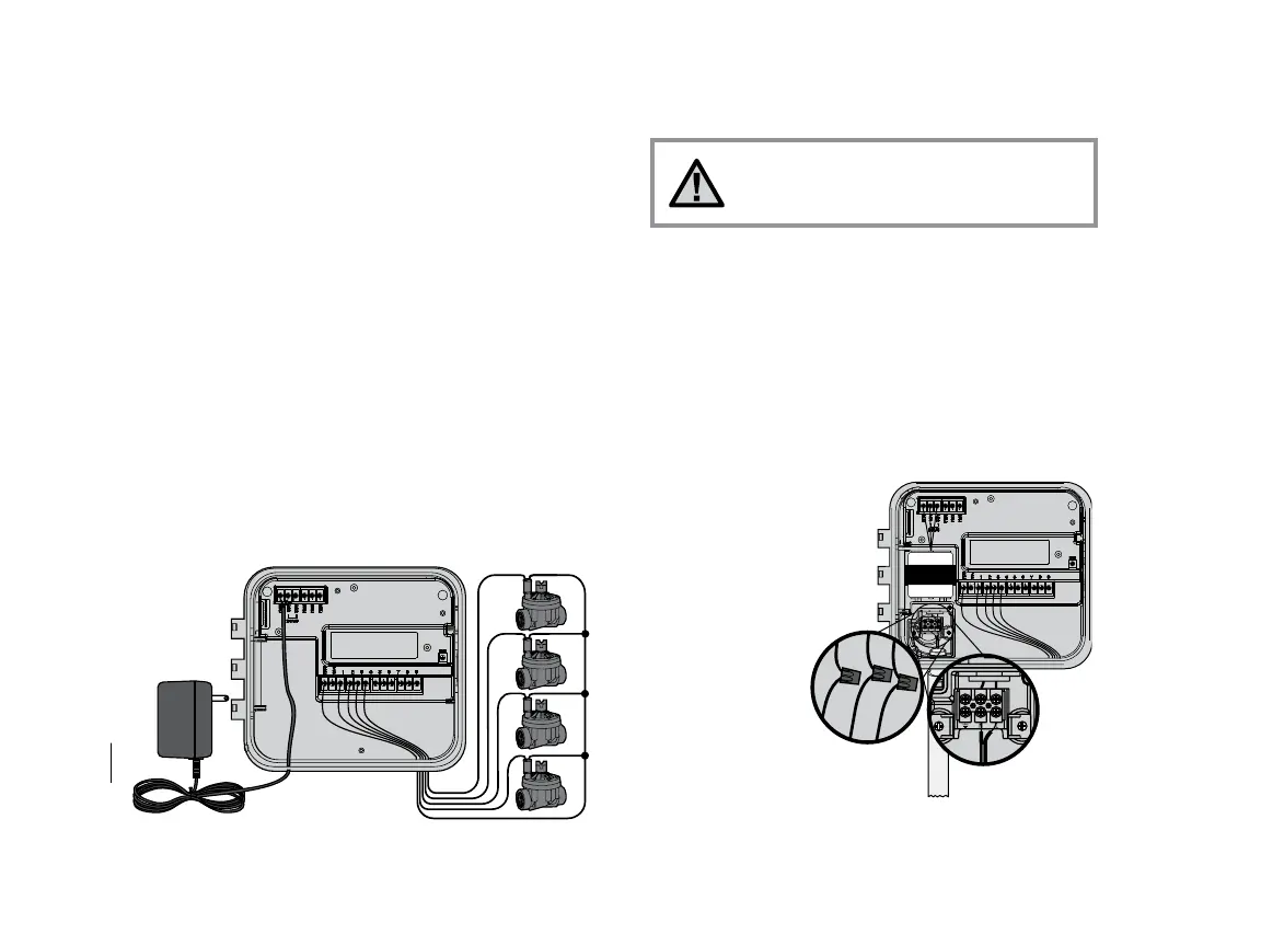
Connect the Two Yellow
Transformer Wires to
the Two AC Terminals
and the Green Wire to
the GND Terminal
1. Route valve wires between control valve location and controller.
2. At valves, attach a common wire to either solenoid wire of all valves.
This is most commonly a white colored wire. Attach a separate
control wire to the remaining wire of each valve. All wire splice
connections should be done using waterproof connectors.
3. Route valve wires through the conduit and attach conduit to one of
the openings on the bottom of the cabinet.
4. Strip ½" (13 mm) of insulation from ends of all wires. Secure valve
common wire to “COM” (Common) terminal. Attach all individual
valve control wires to appropriate station terminals.
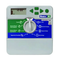
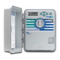
Indoor Cabinet
Route transformer cable through the hole on the bottom left side of the
controller and connect one Yellow Wire to each of the screws marked AC
and the Green Wire to GND.
NOTE: It is recommended that a licensed
electrician perform the following power
installation.
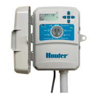
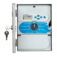
Outdoor Cabinet
Route AC power cable and conduit through the ½"
(13 mm) conduit opening on the left side of the bottom of the cabinet.
Connect the wires to the transformer wires located inside the junction
box. International units are supplied with a built in terminal strip. Always
use a UL listed conduit ½" (13 mm) male adapter when installing
the AC wiring. Insert the adapter into the ½" hole at the bottom of the
controller. Attach a nut to the adapter inside the enclosure.
½" Conduit
for AC Power
230 VAC
(International Models)
120 VAC
(Domestic Models)
HOT
(BLACK)
NEUTRAL
(WHITE)
GROUND
(GREEN)
 Loading...