1X7
1X6
INSTALLATION
HySpeed HT2000LHF Instruction Manual 3-11
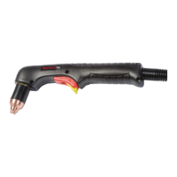
6
Machine V/C Interface Cable – Power Supply
to Machine Interface
1x6 Color Signal
2 Yellow Initial Height Sig. (OFF=Closed)
6 Black Initial Height Com.
11 Shield
4 Orange Auto Height Sig. (OFF=Closed)
8 Black Auto Height Com.
13 Shield
34 Red *†Lifter DOWN Load (DOWN=Closed)
29 Black Lifter DOWN Line
23 Shield
35 Green *†Lifter UP Load (UP=Closed)
30 Black Lifter UP Line
24 Shield
36 Red Upper Limit Switch ( OFF=Closed)
31 Blue Upper Limit Switch
25 Shield
1x6 Color Signal
9 Blue Plasma START (START=Closed)
15 Black Plasma START
14 Shield
37 Red †Arc Transfer (TRANSFER=Closed)
32 Green †Arc Transfer
26 Shield
1 White Hold Ignition Sig. (HOLD=Closed)
5 Black Hold Ignition Com.
10 Shield
3 Brown Ramp Down Error
7 Black Ramp Down Error
12 Shield
1x7 Color Signal
2 White Current 10
3 Red Current 20
4 Green Current 40
5 Orange Current 80
6 Blue Current 100
7 White/Black Current 200
10 Shld Shield
11 Blue/Black Current Common
1x7 Color Signal
16 Black/Red Voltage V5
17 White/Red Voltage V10
18 Orange/Red Voltage V20
19 Blue/Red Voltage V40
20 Red/Green Voltage V80
21 Orange/Green Voltage V100
22 Black/White/Red Voltage V200
23 White/Black/Red Voltage VCommon
Part No. Length
023841 6 ft (1.8 m)
023842 15 ft (4.6 m)
023843 25 ft (7.6 m)
023844 35 ft (10.7 m)
023845 50 ft (15 m)
123047 60 ft (18.3 m)
023846 75 ft (23 m)
Part No. Length
123080 85 ft (25.9 m)
023847 100 ft (30.5)
023962 115 ft (35.1 m)
123148 120 ft (36.6 m)
023848 125 ft (38.1 m)
023849 150 ft (46 m)
023850 200 ft (62 m)
4 4
5 5
* Signals are AC relays. DC relays are available as an option from Hypertherm by ordering kit: 128404
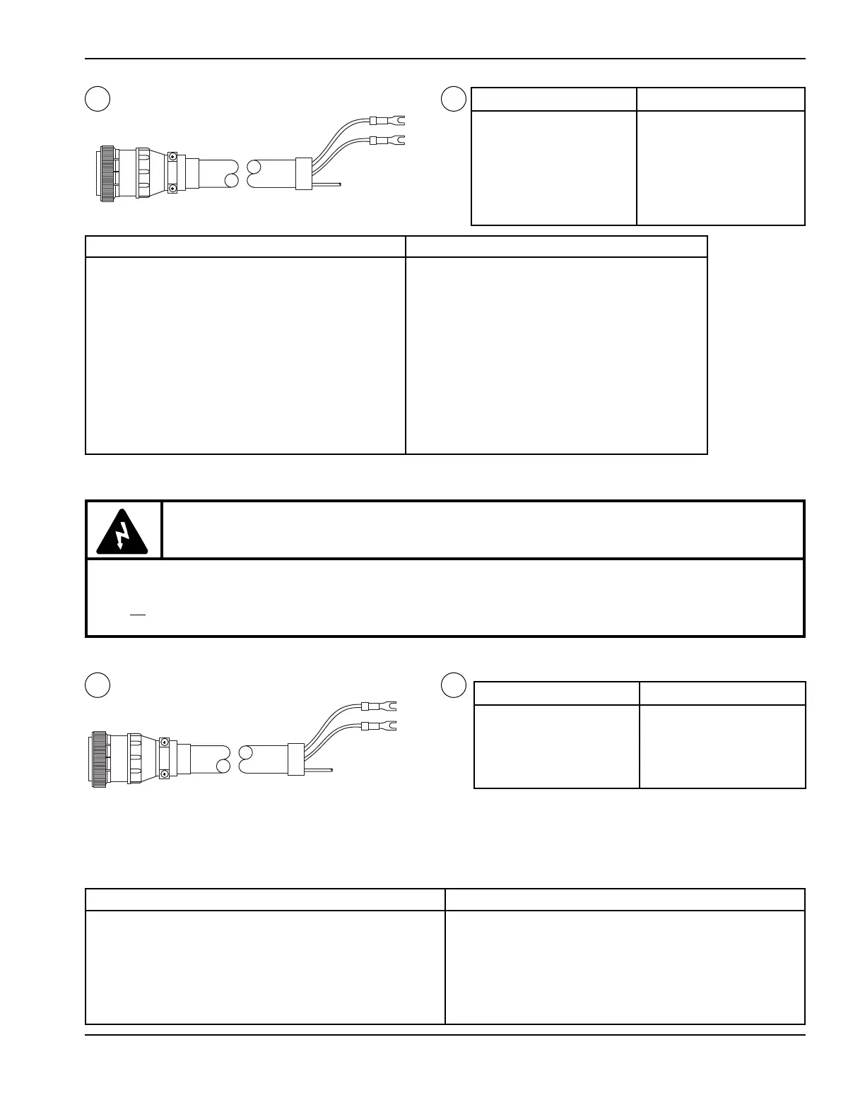
Machine I/O Interface Cable – Power Supply
to Machine Interface
Part No. Length
023902 6 ft (1.8 m)
023851 15 ft (4.6 m)
023852 25 ft (7.6 m)
023853 35 ft (10.7 m)
023854 50 ft (15 m)
Part No. Length
023855 75 ft (23 m)
023856 100 ft (30.5)
023903 125 ft (38.1 m)
023857 150 ft (46 m)
023858 200 ft (62 m)
WARNING
When installing or servicing the power supply, AC or DC line voltages may be present on the UP,
DOWN and TRANSFER signals even if the power supply line disconnect switch is OFF. Make certain
that all line disconnect switches relating to the system are OFF during installation and when servicing.
Note: If you are using a remote V/C to set voltage and current, skip this step.
Before connecting the machine V/C interface cable, see the wiring diagrams in this manual and verify that
the correct plug is attached to the µP control PCB REC6 receptacle.
 Loading...