OPERATION
HySpeed HT2000LHF Instruction Manual 4-29
Shield Arc Approx.
Material
Plasma Gas Flow Rate %
Gas (Air) Torch-to-work Initial Torch Voltage Motion
Thickness Preflow Cutflow Pressure Distance Piercing Height Setting Travel Speed Delay Time
(inches) (mm) (O
2
%N
2
%) (O
2
%N
2
%) (psi) (inches) (mm) (inches) (mm) (volts) (ipm) (mm/min.) (sec)
1/4 6 12 38 64 0 60 1/8 3 1/4 6 115 160 4060 0.5
.315 8 (14.9 / 50.4 (79.6 / 0 (270 1/8 3 1/4 6 120 120 3000 0.5
3/8 10 SCFH) SCFH) SCFH) 1/8 3 1/4 6 120 100 2540 1.0
1/2 12 .157 4 .314 8 120 80 2030 2.0
5/8 15 .157 4 .314 8 125 70 1780 2.0
3/4 20 3/16 5 3/8 10 130 55 1400 2.5
7/8 22 1/4 6 1/2 12 135 45 1140 2.5
1 25 1/4 6 1/2 12 135 35 890 2.5
1 1/4 32 1/4 6 140 22 560
1-1/2 38 1/4 6 150 15 380
1-3/4 44 5/16 8 160 10 250
2 50 5/16 8 170 7 180
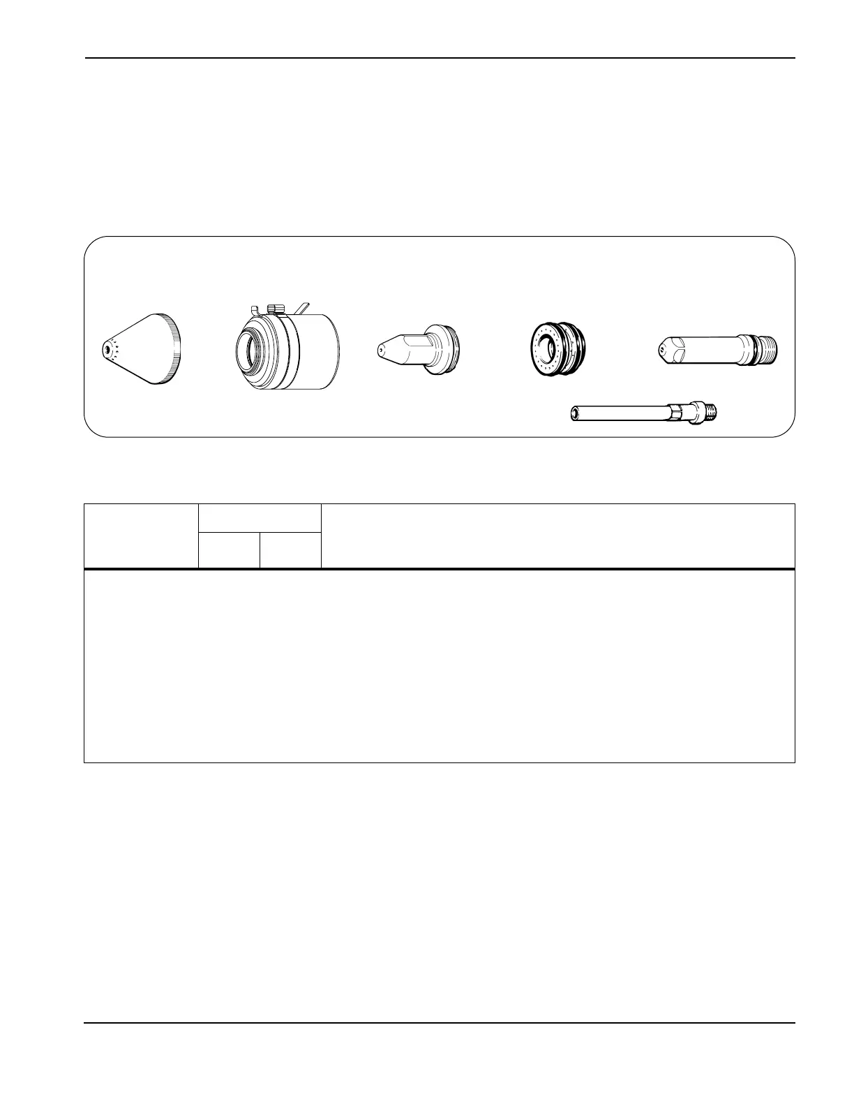
Mild Steel - Beveling Consumables
200 amps • O
2
Plasma / Air Shield
Notes: Set oxygen plasma gas inlet pressure to 120 psi (8.3 bar).
Set nitrogen plasma gas inlet pressure to 120 psi (8.3 bar).
Set shield gas inlet pressure to 90 psi (6.2 bar).
Production cutting above 1" (25 mm) not recommended
Beveling cuts should be made between 45° and 90° to the work surface.
Above Water Only
120833 (cw)
120834 (ccw)
Swirl ring
120258
Electrode
120257
Water Tube
120259
Nozzle
120837
(cw)
120838 (ccw)
Retaining cap
120260
Shield
7
 Loading...