MAINTENANCE AND REPAIR
powermax
45
Operator Manual 5-9
Replacement
1. Hold the Mylar barrier so that the edge
with the 3 notches is on the left and the
edge with 4 notches is on the right.
2. There is a perforation across the top,
about 1.75 inches (4.45 cm) down from
the top edge. If you are replacing the
Mylar barrier with a new one, you will
need to fold it along this perforation so
that the top edge bends away from you.
3. Position the barrier so that the folded
section will cover the top of the power
board. Slide the barrier into place with
the bottom edge between the ribs on the
base and the power board. The notches
on each side of the barrier should align
with the ribs on the inside of the endcaps.
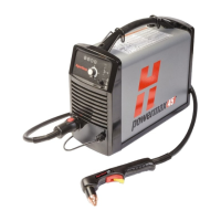
4. Being careful not to pinch any of the
wires, slide the cover back onto the
power supply. Make sure that the bottom
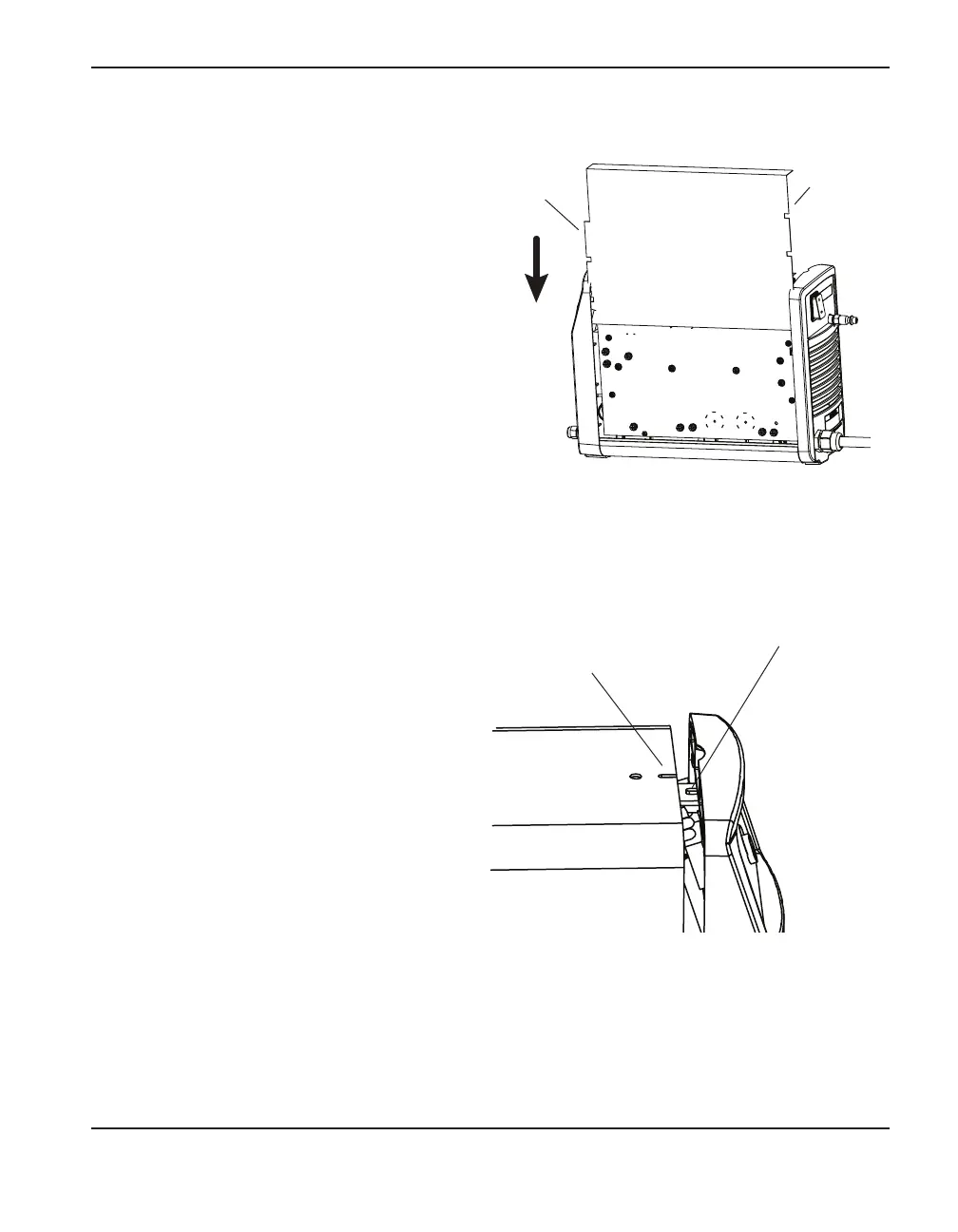
edges are in the tracks and that the slot
in the top of the cover is aligned with
the tab on the front endcap so that the
louvers in the cover are in front of the fan.
Position the handle over the holes in the
top of the cover, then secure the cover
with the 2 screws.
Three
notches
Cover slot
Tab
Four
notches
 Loading...


