MAINTENANCE AND REPAIR
5-10 powermax
45
Operator Manual
TP 19
W
-
+
-
+
TP 18
R
TP 17
B
192 VDC
192 VDC
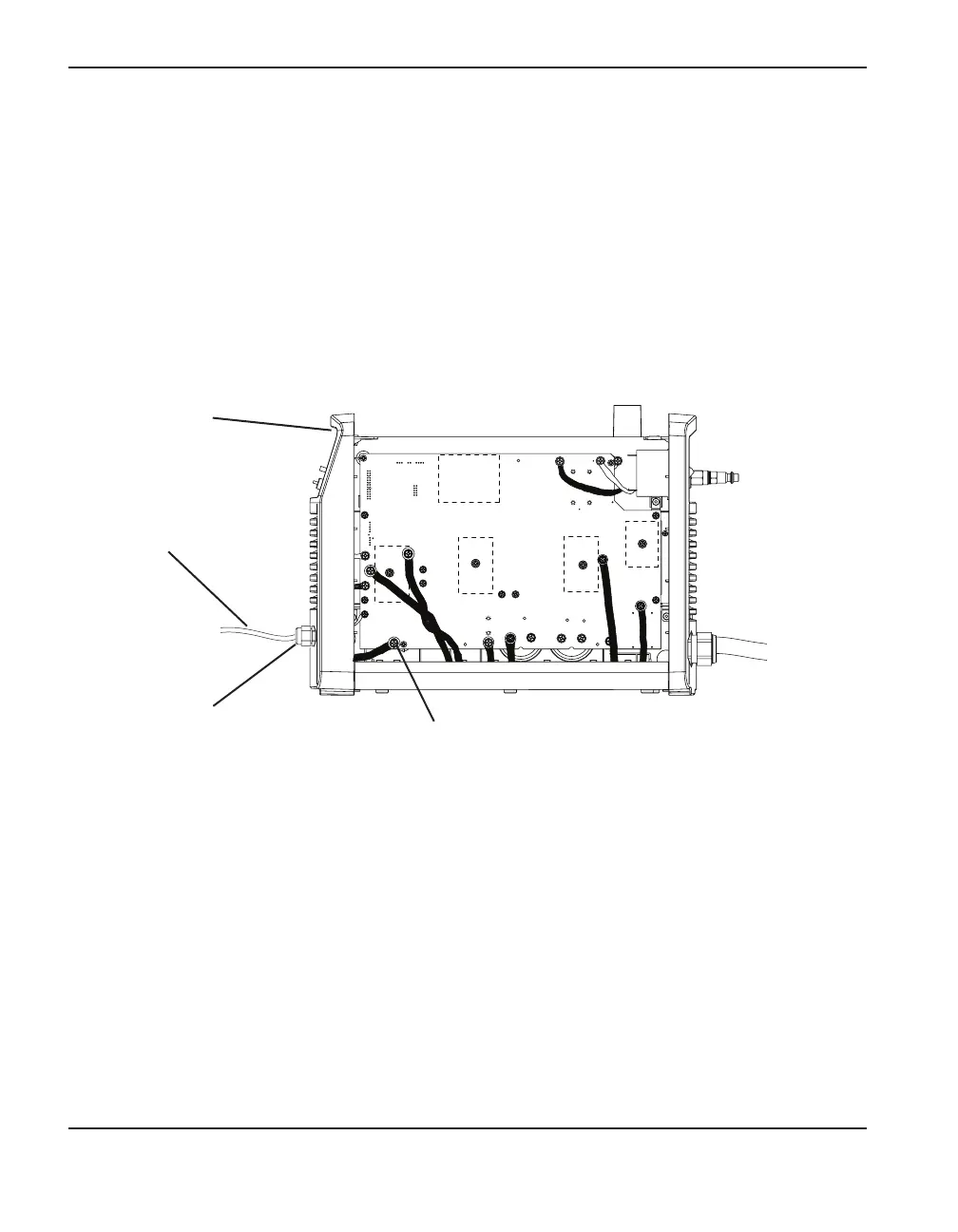
Replace the work lead (CSA and CE)
1. Turn OFF the power, disconnect the power cord, and disconnect the gas supply.
2. Remove the cover from the power supply and remove the Mylar barrier from in front of the
power board.
3. Remove the screw from J21 (also labeled “work lead”) on the power board that attaches the
lead to the board. Set the screw aside.
Work lead
Work lead connection to
power board (J21)
Front panel
Strain relief
4. Gently tilt the front panel away from the power supply. From the inside of the panel, unscrew the
nut that secures the strain relief to the endcap.
5. Thread the connector end of the new work lead through the front panel and fit the strain relief
into the hole in the panel.
6. Slide the nut over the work lead’s connector. Gently tilt the front panel away from the power
supply and screw the nut onto the strain relief.
7. Attach the work lead to the power board at J21 using the screw that you removed earlier. The
torque setting for this connection is 20 inch-pounds (23.4 kg cm)
8. Realign the front panel.
 Loading...


