Important: You can remove a drive assembly without powering off the expansion
enclosure. However, to maintain operating temperature, perform the following
tasks.
v Do not remove a faulty drive assembly until its replacement is ready to be
installed.
v Do not keep the cover off an operational enclosure for more than 15 minutes.
The reduction in airflow through the enclosure might cause the enclosure or its
components to shut down to protect from overheating.
About this task
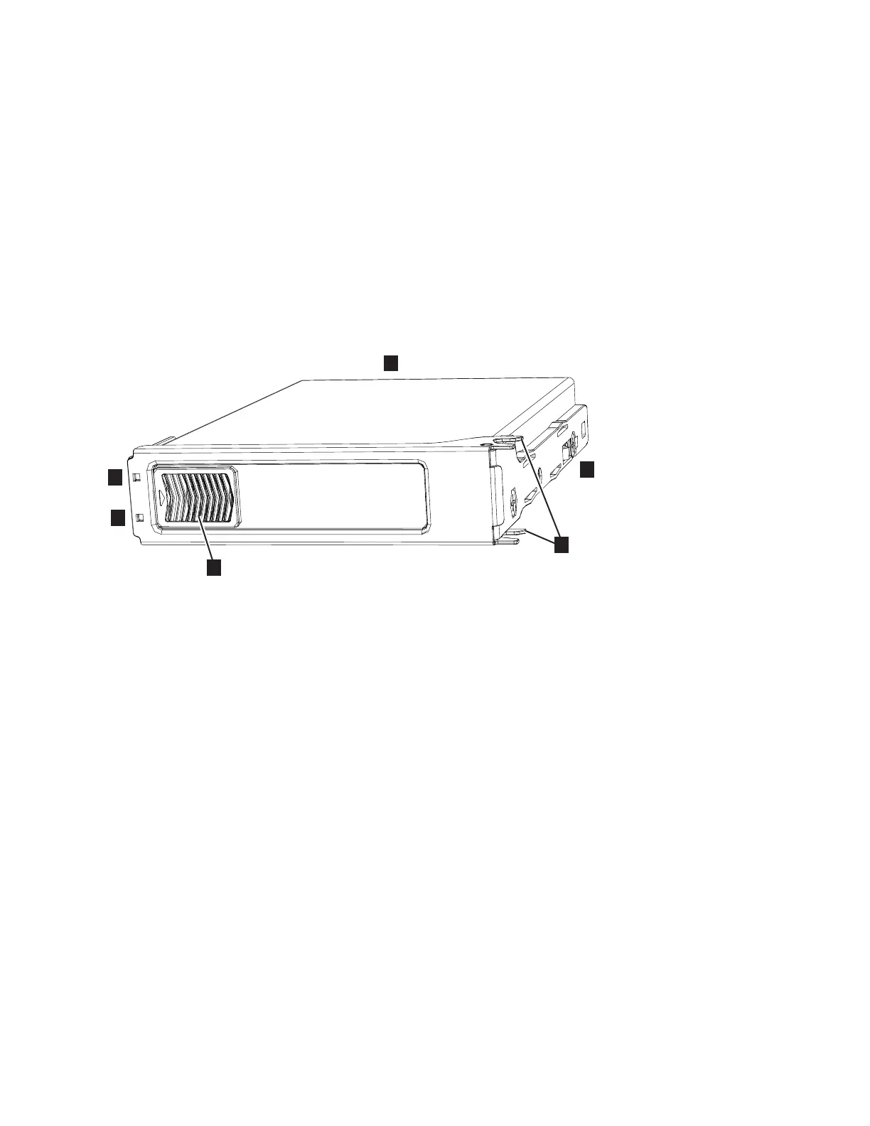
The 2076-92F expansion enclosure supports 92 drives. Figure 90 shows an example
of a drive assembly.
▌1▐ Disk drive
▌2▐ Online indicator
▌3▐ Fault indicator
▌4▐ Release latch
▌5▐ Drive latch toes
▌6▐ Drive carrier
Procedure
1. Read all available safety information.
2. Use the slide rails to pull the enclosure out from the rack, as described in
“Removing an expansion enclosure from a rack: 2076-92F” on page 92.
3. Remove the top cover, as described in “Removing the top cover: 2076-92F” on
page 44.
4. Locate the slot that contains the drive assembly that you want to remove.
Note: When a drive is faulty, the amber fault indicator is lit (▌3▐ in Figure 90).
Do not replace a drive unless the drive fault indicator is on or you are
instructed to do so by a fix procedure. When lit, the green indicator shows that
activity is occurring on the drive.
A label on the enclosure cover (Figure 91 on page 104) shows the location of the
drive slots. The drive slots are numbered 1-14 from left to right and A-G from
the back to the front of the enclosure.
Figure 90. Drive assembly
Chapter 2. Installing the Storwize V7000 Gen2 and Storwize V7000 Gen2+ hardware 103
 Loading...


