Table 15. Display panel LEDs (continued)
Function Color Status Description
Enclosure fault Amber On The expansion
enclosure is coming
up or a fault is
detected against a
component within
the enclosure.
Off No faults are
detected.
The 2076-92F expansion enclosure contains two PSUs (▌4▐ in Figure 120 on page
132) that are accessible from the front of the enclosure. Each PSU has its own a set
of LEDs, as shown in Figure 121.
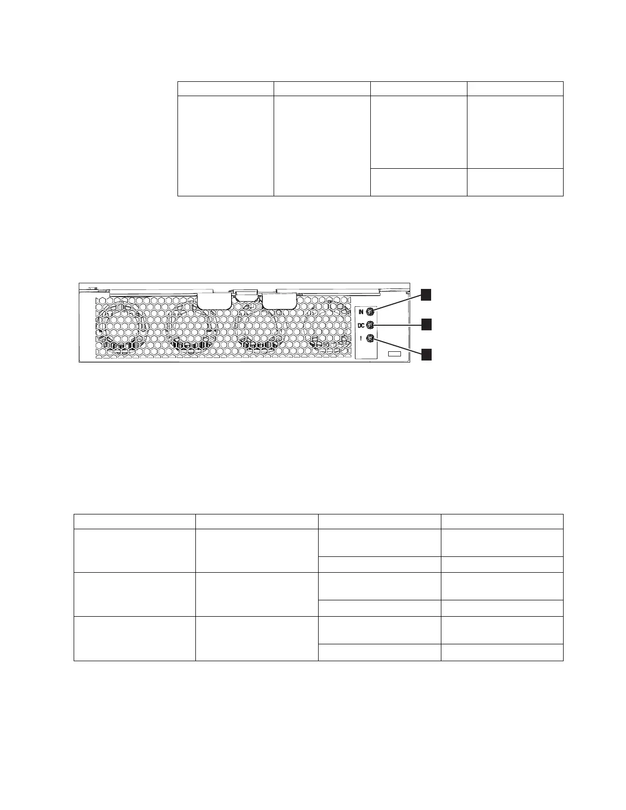
▌1▐ Input power
▌2▐ DC power
▌3▐ Fault indicator
Table 16 explains the function and status that is indicated by each of the LEDs. The
power cords for each PSU are accessible from the rear of the expansion enclosure
(▌1▐), as shown in Figure 124 on page 136.
Table 16. Power supply unit LEDs
Function Color Status Description
▌1▐ Input power Green On The input voltage is within
specification.
Off No power input detected.
▌2▐ DC power Green On DC power outputs are
within specification.
Off DC power is not available.
▌3▐ Fault Amber On A fault is detected in the
PSU.
Off No faults are detected.
LEDs inside of the expansion enclosure
Each of the drives and secondary expansion modules within the 2076-92F
expansion enclosure has two LED indicators. To view the drives and secondary
expansion modules, you must remove the cover of the enclosure, as described in
“Removing the top cover: 2076-92F” on page 44.
Figure 121. LEDs on the front of a power supply unit
Chapter 2. Installing the Storwize V7000 Gen2 and Storwize V7000 Gen2+ hardware 133
 Loading...


