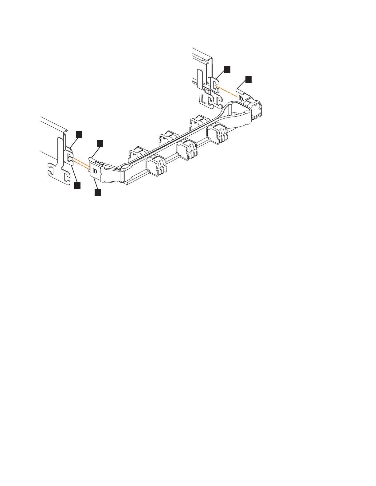
▌1▐ Inner connector on the upper CMA
▌2▐ Connector base on inner rail member
▌3▐ Outer connector on the upper CMA
▌4▐ Connector base on outer rail member
▌5▐ Support rail connector on the upper CMA
▌6▐ Connector base on outer rail member
1. Press the latch on the connector base on the upper CMA assembly (▌5▐ in
Figure 45).
2. Pull the connector to remove it from the connector base on the right support
rail (▌6▐ in Figure 45).
3. Press the latch on the outer connector of the upper CMA assembly (▌3▐ in
Figure 45).
4. Remove the outer connector from the inner member of the left support rail (▌4▐
in Figure 45).
5. Remove the inner connector of the upper CMA assembly (▌1▐) from the inner
member of the left support rail (▌2▐), as shown in Figure 45.
Remove the lower CMA assembly
Note: The procedure for removing the lower CMA assembly is the same as the
procedure to remove the upper CMA assembly. However, the connector locations
are reversed. For example, the connector base of the upper CMA (▌5▐ in Figure 45)
connects to the right rail. The connector base of the lower CMA (▌11▐ in Figure 46
on page 61) attaches to the left rail.
Figure 45. Connectors for the upper cable management arm
60 Storwize V7000 Gen2 and Gen2+: Quick Installation Guide
 Loading...


