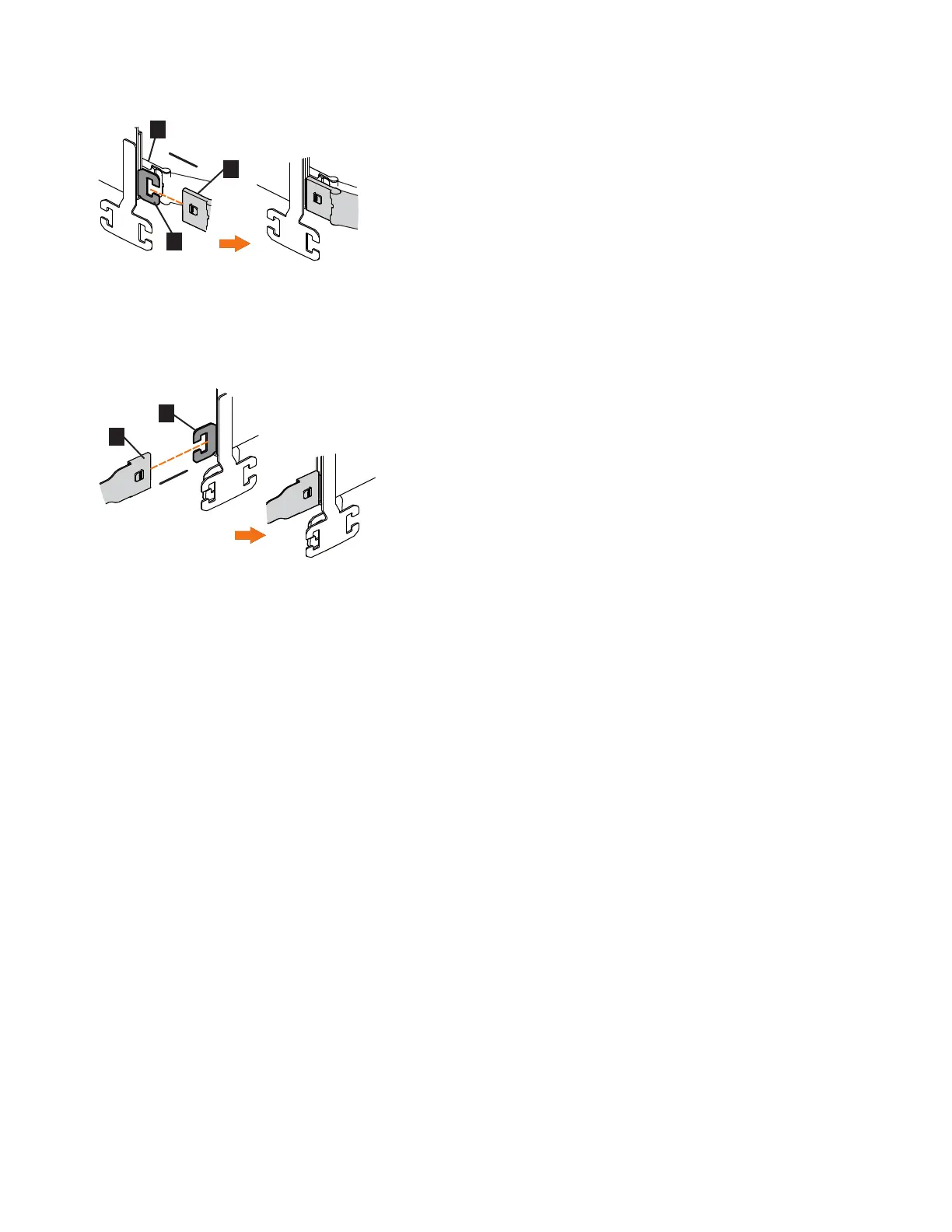
4. Attach the support rail connector on the upper CMA assembly (▌5▐) to the
connector base on the right support rail (▌6▐), as shown in Figure 56.
Ensure the cable-management arm connector attaches securely to the hooks on
the rails.
Installing the lower CMA assembly
Note: The procedure for attaching the lower CMA assembly is the same as the
procedure to attach the upper CMA assembly. However, the connector locations are
reversed. For comparison, Figure 57 on page 67 shows the upper and lower CMA
assemblies as they are aligned to the support rails. The support rail connector of
the upper CMA attaches to the right rail. The support rail connector of the lower
CMA ▌11▐ attaches to the left rail.
Figure 55. Install the inner connector of the upper CMA to the inner member of the support rail
Figure 56. Attach the support rail connector of the upper CMA to the right support rail
66 Storwize V7000 Gen2 and Gen2+: Quick Installation Guide
 Loading...


