28
6
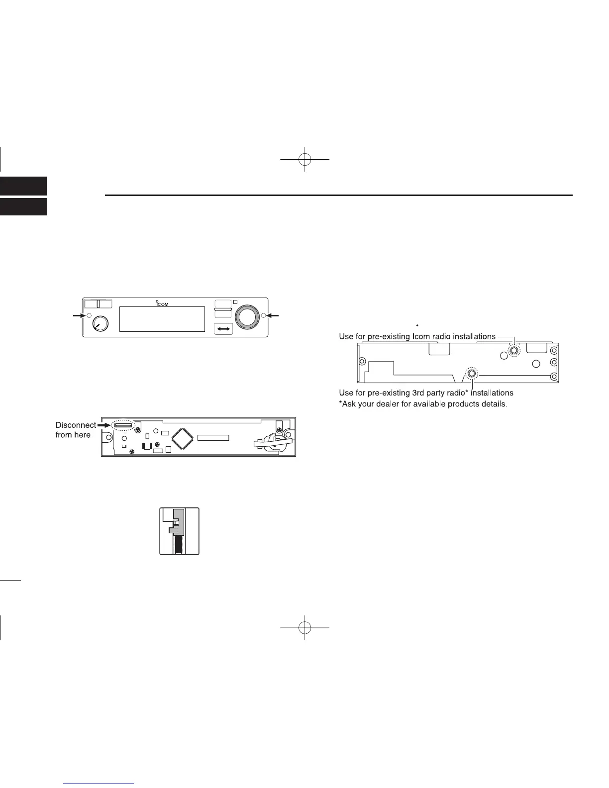
INSTALLATION AND REMOVAL
■ Transceiver installation
q Insert a
3
/
32
in allen wrench into the 2-holes in the front
panel.
w Turn the wrench counterclockwise until the front panel is
loose.
•Acable connects the front panel with the main unit.
e Disconnect the flat cable from the front panel’s connector
to remove the front panel.
r Visually confirm that the metal catches on the top and bot-
tom of the transceiver are as shown below.
t Turn the wrench clockwise until the main unit is fixed to the
installation rack.
•Turn the wrench in the upper socket as shown below when using
the installation rack for Icom products.
•Turn the wrench when in the lower socket as shown below when
using the installation rack for 3rd party* products.
y Replace the disconnected cable and removed front panel
in place.
■
Transceiver removal
The IC-A210 may easily be removed from the installation
rack, if desired.
q Perform the same steps as q–e of “Transceiver installa-
tion” to remove the front panel (See the left column).
w Turn the wrench counterclockwise until the main unit
moves slightly from the installation rack.
•See t of “Transceiver installation” for details.
e Pull out the transceiver slowly from the installation rack.

 Loading...


