2001 NEW
5
1
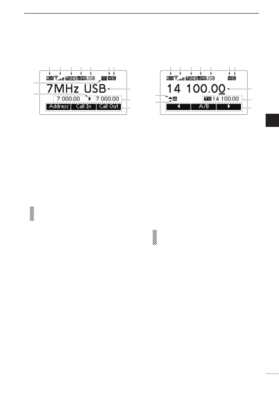
PANEL DESCRIPTION
1
2
3
4
5
6
7
8
9
10
11
12
13
14
15
16
17
Quick Reference
q RECEIVE/TRANSMIT ICON
➥ “ RX” appears when signals are received or the
squelch is open.
➥ “ TX” appears when transmitting.
w S-METER/TX METERS
➥ Displays the receive signal strength.
➥ Displays the transmit output power.
e TUNE ICON
Appears after the automatic antenna tuner matches
the transceiver and antenna.
NOTE:
Appears only when the frequency is set to within
±1% of the tuned frequency.
r OUTPUT POWER ICON
➥ “HI” appears when high power is selected.
➥ “MID” appears when mid power is selected.
➥ “LOW” appears when low power is selected.
t OPERATING MODE INDICATOR
Displays the selected operating mode.
• “LSB,” “USB,” “CW,” “AM,” RTTY,” “LSBD1,” “USBD1,”
“LSBD2,” “USBD2,” “LSBD3” or “USBD3” appears, de-
pending on the operating mode.
Selectable operating modes differ depending on the
transceiver version and/or presetting.
y MUTE ICON
➥ “S” appears when the Call squelch function is se-
lected.
➥ “L” appears when the S-meter squelch is se-
lected.
➥ “V” appears when the Voice squelch is selected.
u CLEAR TALK ICON
Appears when the Clear Talk function is ON.
i MAIN READOUTS
<Memory Channel display>
Displays the channel name.
<VFO display>
Displays the operating frequency.
o SUB READOUTS
<Memory Channel display>
Displays the selected information.
• ‘Frequencies,’ ‘Latitude and Longitude,’ ‘Direction and El-
evation,’ ‘Antenna SWR and Power source voltage’ and
‘Date and Time’ can be displayed.
‘Latitude and Longitude’ and ‘Direction and Elevation’ re-
quire data from a GPS unit.
• When the frequencies are displayed, the receive fre-
quency is displayed on the right and the transmit fre-
quency is displayed on the left.
• “u” appears beside the receive or transmit frequencies,
and indicates which one is active.
• “p” or “q” appears instead of “u” to the right of the re-
ceive frequency, when the Clarifier function is ON, and it
indicates the upper or lower shift.
NOTE: No transmit frequency is displayed when
the selected channel is configured as “receive
only.”
<VFO display>
Shows the transmit or receive frequency when VFO
split is ON.
!0 FUNCTION DISPLAY
Displays the function of the [§], [§§] and [§§§] func-
tion keys.
!1 VFO ICON
<VFO display>
➥ “A” appears when VFO A is selected.
➥ “B” appears when VFO B is selected.
!2 CLARIFIER ICON
<VFO display>
“p” or “q” appears when the Clarifier function is
ON, and indicates the upper or lower shift.
• Memory Channel Display • VFO Display
q w r t yu q w r t y ue e
!1
!3
!2
i
o
i
o
!0 !0
!2
■ LCD screen
Continued on the next page.
 Loading...