76
6
CONNECTION AND INSTALLATION
2001 NEW 2001 NEW
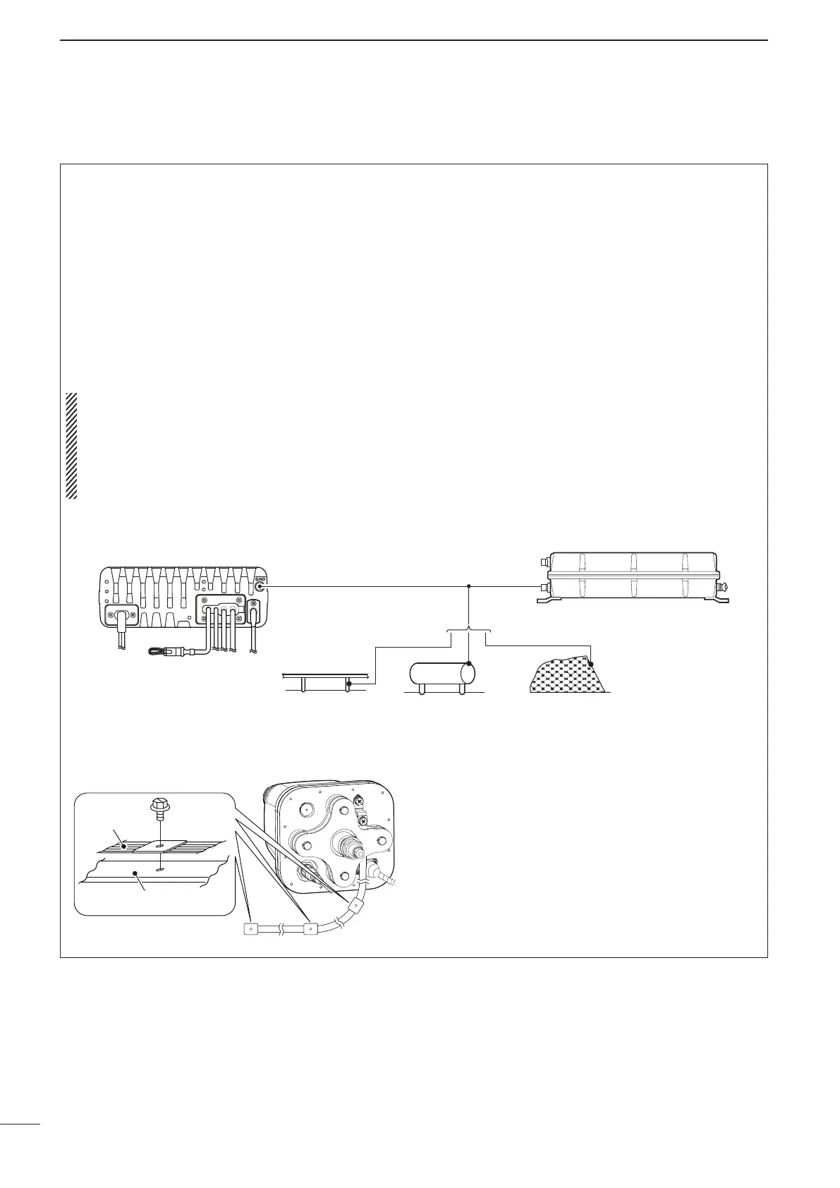
■ Ground connection
The transceiver and antenna tuner MUST have an
adequate RF ground connection. Otherwise, the
overall efficiency of the transceiver and antenna
tuner installation will be reduced. Electrical shocks
and interference from other equipment could occur.
In marine installations, electrolysis could also occur.
For best results, use a 50 or 75 mm (2 or 3 inches)
wide copper strap, and make the connection as short
as possible. Ground the transceiver and antenna
tuner to the same ground point, otherwise the volt-
age difference (at the RF level) between two ground
points may cause electrolysis.
RWARNING! When grounding to a metal ship hull
Use Zinc anodes to protect the hull from electroly-
sis.
Ask your dealer, technical installer or refer to a
technical book, and so on, for RF grounding de-
tails.
• Ground system example
Best ground points
• External ground plate
• Copper screen
• Copper foil
Unusable ground points
( These connections may cause an explosion or electrical
shock)
• Gas or electrical pipe
• Fuel tank or oil-catch pan
Copper pipe Metal object Copper screen
AT-140
Transceiver
• About the ground strap connection for the AH-740
Ground
strap
Vehicle chassis or body
 Loading...