2001 NEW
77
6
CONNECTION AND INSTALLATION
6
■ Power source
The transceiver requires regulated DC power of
13.8 V and at least 28 A. There are two ways to sup-
ply power:
• Direct connection to a 12 V battery in your vehicle
through the supplied DC power cable.
• Use a DC power supply connected to an AC outlet.
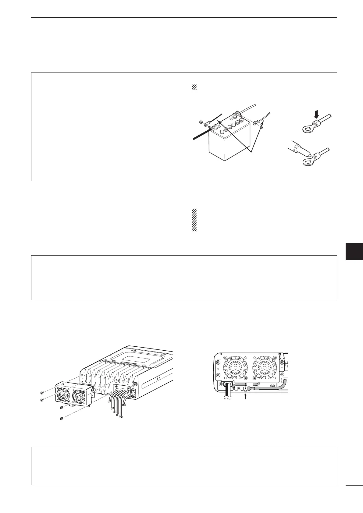
DC power cable connection
NOTE: Use terminals for the cable connection.
12 V
battery
Supplied
DC power cable
+ red
_ black
Crimp
Solder
■ Antenna
Many stations operate with a whip or long wire (insu-
lated back stay) antenna. However, these antennas
cannot be connected directly to the transceiver since
their impedance may not match with the transceiver
antenna connector.
RDANGER HIGH VOLTAGE!
NEVER touch the antenna element/wire while tun-
ing or transmitting.
q Attach the Cooling fan to the transceiver’s heat-
sink, and tighten the 4 supplied M3 × 8 mm screws.
w Secure the connector and cables using the sup-
plied cable tie.
D AT-140 automatic antenna tuner
See page 75.
D AH-740
automatic tuning antenna
See page 75.
D Non-Icom tuner
Some non-Icom tuners may be used with the IC-
F8101. Please consult your dealer if you wish to use
one.
■ CFU-F8100 (Optional Cooling Fan)
For Users in California (U.S.A.)
This CR1632 Lithium Battery contains Perchlorate Material—special handling may apply.
See http://www.dtsc.ca.gov/hazardouswaste/perchlorate
 Loading...