78
6
CONNECTION AND INSTALLATION
2001 NEW 2001 NEW
The RMK-6 allows you to install the IC-F8101’s Front
panel separately from the Main unit for added installa-
tion convenience and operation. Use either the optional
OPC-607, OPC-608, OPC-609 or OPC726
separation
cable
with the RMK-6.
The RMK-6 is the same as the one supplied in the
Separated type transceiver.
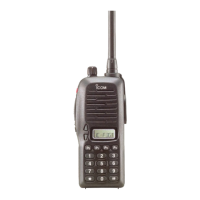
D Supplied Accessories
Flat washers
(M5)
RMK-6 with Mounting
bracket
Spring washers
(M5)
Mounting screws
(M5 × 12 mm)
Cable clamps
(Screws M2.6 × 5 mm)
Self-tapping screws
(M5 × 16 mm)
Screws
(M3 × 8 mm)
Hex socket screws
Nuts
(M5)
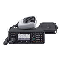
D Separation
The optional OPC-607 (3 m; 9.8 ft), OPC-608 (8 m;
26.2 ft), OPC-609 (1.9 m; 6.2 ft) or OPC-726 (5 m;
16.4 ft) separation cable is required for separately in-
stalling the transceiver Front panel and Main unit.
q First, make sure the transceiver’s power is OFF,
then disconnect the DC power cable.
w Remove the knob bolts and mounting bracket from
the RMK-6.
e Unscrew the 4 hex socket screws using an allen
wrench, then remove the Front panel from the trans-
ceiver in the direction of the arrow.
• Separate the RMK-6’s Front panel attachment and Main
unit attachment in the same way.
RMK-6
Transceiver
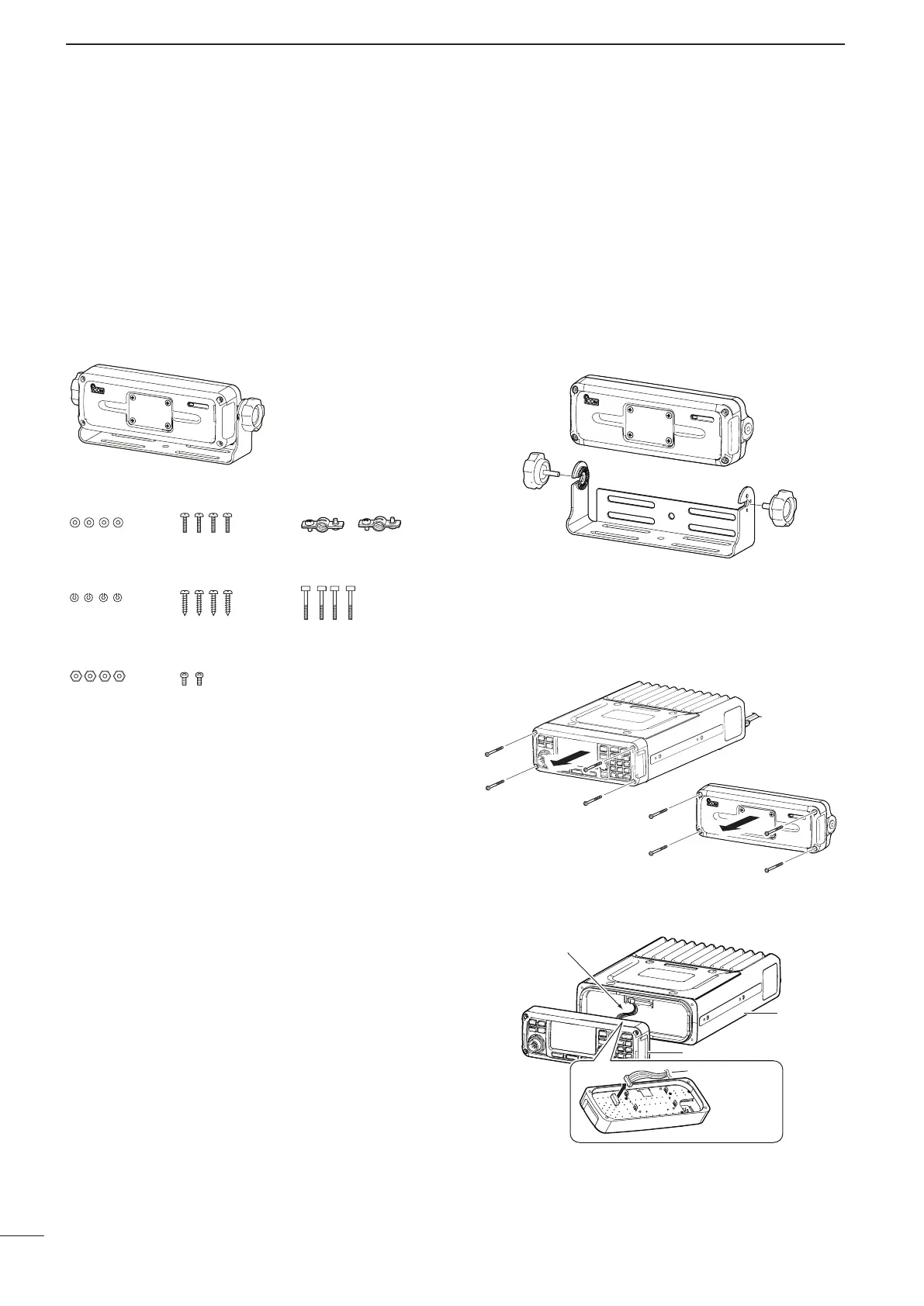
r Disconnect the connection cable from the Front
panel.
Front panel
Connection cable
Connection cable
Main unit
Front panel
■ RMK-6 (Optional Separation kit)
 Loading...