84
6
CONNECTION AND INSTALLATION
2001 NEW
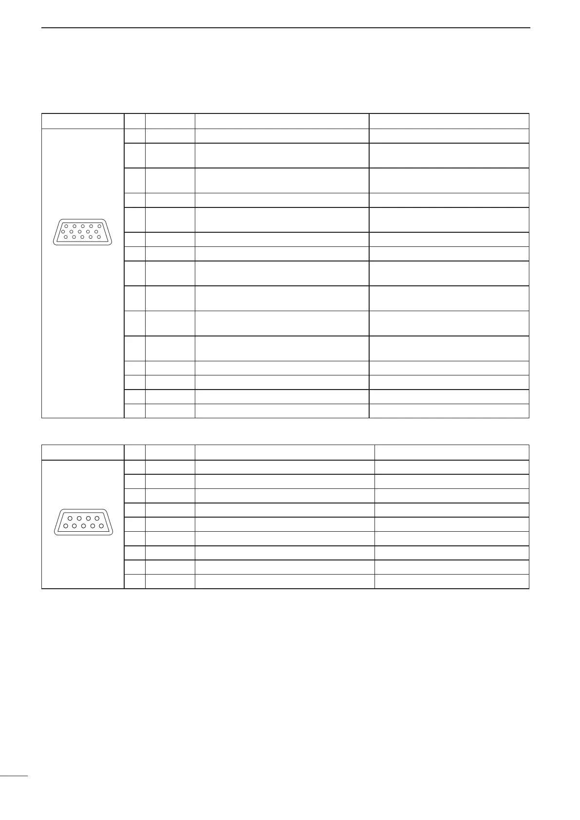
■ Connector information
ATU Pin Pin name Description Specification
1 KEY Key signal input. —
2 START Start/bypass signal output. —
3 13.8V 13.8 V output for Antenna tuner. 13.8 V, maximum 2 A
4 13.8V 13.8 V output for Antenna tuner. 13.8 V, maximum 2 A
5 GND Connect to ground. —
6 GND Connect to ground. —
7 NC — —
8 NC — —
9 NC — —
ACC Pin Pin name Description Specification
1 CI-V — —
2 AF IN Input terminal for the AF signal.
Input sensitivity (Data mode):
More than 52.5 W at 100 mV
3 AF OUT Output terminal for the AF signal.
Output level: 200 to 400 mVrms
when receiving Data mode
4 AF GND Ground line for the AF signal. —
5 GPS RXD
Input terminal for receive data from GPS
unit.
NMEA0183
6 NC — —
7 RELAY Goes to ground when transmitting. Less than 100 mV
8 EALC ALC voltage input.
Control sensitivity (at –3 V input):
More than 40 dB suppression
9 MODPTT
PTT input terminal.
When grounded, transmits.
Input voltage: Less than 0.8 V
for transmit
10 CW KEY CW and FSK keying input.
CW: Less than 0.6 V for transmit
RTTY: Open=Mark
11 EALARM Output terminal for the Alarm signal.
Output current: 12 mA±10%
Open collector
12 GND Connect to ground. —
13 5V 5 V output for GPS unit. 5 V, maximum 200 mA
14 NC — —
15 13.8V 13.8 V output for external equipment. 13.8 V, maximum 1 A
 Loading...