Panel Description
⓰ ANI CLEAR SWITCH [ANI CLR]
ANI CLEAR SWITCH [ANI CLR]ANI CLEAR SWITCH [ANI CLR]
ANI CLEAR SWITCH [ANI CLR]
Push for 1 sec. to clear the received ANI ID indication
on the display and returns to original indication.
▒ NOTE:
NOTE: NOTE:
NOTE: This switch is no function available for some
▒ versions.
⓱ DEALER
DEALERDEALER
DEALER-
--
-PROGRAMMABLE SWITCH [PROG]
PROGRAMMABLE SWITCH [PROG]PROGRAMMABLE SWITCH [PROG]
PROGRAMMABLE SWITCH [PROG]
Toggles the pre-programmed function ON or OFF
when pushed.
⓲ PROGRAMMED FUNCTION INDICATOR
PROGRAMMED FUNCTION INDICATORPROGRAMMED FUNCTION INDICATOR
PROGRAMMED FUNCTION INDICATOR
Lights green while pre-programmed function is
activated.
⓳ DC INDICATOR
DC INDICATORDC INDICATOR
DC INDICATOR
Lights green when in DC operation.
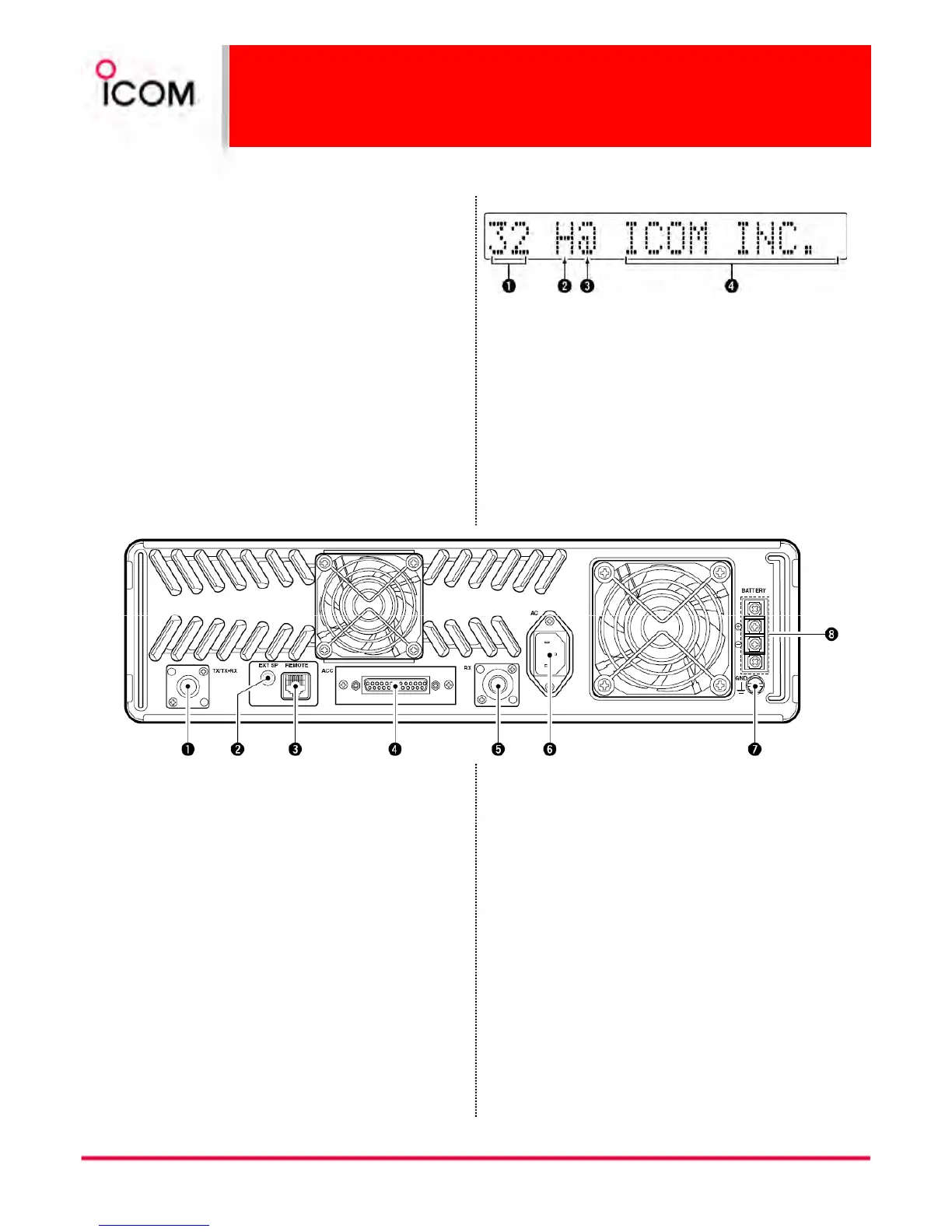
❶ MEMORY CHANNEL INDICATOR
MEMORY CHANNEL INDICATORMEMORY CHANNEL INDICATOR
MEMORY CHANNEL INDICATOR
Shows the selected memory channel.
❷ TRANSMIT POWER INDICATOR
TRANSMIT POWER INDICATORTRANSMIT POWER INDICATOR
TRANSMIT POWER INDICATOR
Shows the output power level.
❸ AUDIBLE INDICATOR
AUDIBLE INDICATORAUDIBLE INDICATOR
AUDIBLE INDICATOR
“@” appears in an audible condition, disappears in
an inaudible condition. (When an audible condition,
audio mute is cancelled.)
❹ ALPHANUMERIC INDICATORS
ALPHANUMERIC INDICATORSALPHANUMERIC INDICATORS
ALPHANUMERIC INDICATORS
Shows the variety text or code information.
Function display
Function displayFunction display
Function display
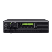
Rear panel
Rear panelRear panel
Rear panel
12
❶ TRANSMIT ANTENNA CONNECTOR [TX/TX•RX]
TRANSMIT ANTENNA CONNECTOR [TX/TX•RX]TRANSMIT ANTENNA CONNECTOR [TX/TX•RX]
TRANSMIT ANTENNA CONNECTOR [TX/TX•RX]
➥Connects a transmit antenna (impedance: 50 Ω)
and outputs transmit signals.
➥When installing an optional internal duplexer
(supplied by third party), this connects the
transmit receive to an antenna.
❷ EXTERNAL SPEAKER CONNECTOR [EXT SP]
EXTERNAL SPEAKER CONNECTOR [EXT SP]EXTERNAL SPEAKER CONNECTOR [EXT SP]
EXTERNAL SPEAKER CONNECTOR [EXT SP]
Accepts a 4 Ω external speaker.
❸ REMOTE CONNECTOR [REMOTE]
REMOTE CONNECTOR [REMOTE]REMOTE CONNECTOR [REMOTE]
REMOTE CONNECTOR [REMOTE]
Connects to the remote controller.
• See p. 16 for remote connector information.
❹ ACCESSORY CONNECTOR [ACC]
ACCESSORY CONNECTOR [ACC]ACCESSORY CONNECTOR [ACC]
ACCESSORY CONNECTOR [ACC]
Connects to the remote controller.
• See pgs. 15 for accessory connector information.
❺ RECEIVE ANTENNA CONNECTOR [RX]
RECEIVE ANTENNA CONNECTOR [RX]RECEIVE ANTENNA CONNECTOR [RX]
RECEIVE ANTENNA CONNECTOR [RX]
➥Connects a receive antenna (impedance: 50 Ω)
and inputs receiving signals.
➥When installing an internal duplexer (supplied by
third party), do not use this connector.
❻ AC POWER SOCKET [AC]
AC POWER SOCKET [AC]AC POWER SOCKET [AC]
AC POWER SOCKET [AC]
Connects the supplied AC power cable to a domestic
AC outlet.
❼ GROUND TERMINAL [GND]
GROUND TERMINAL [GND]GROUND TERMINAL [GND]
GROUND TERMINAL [GND]
Ground the repeater through this terminal to prevent
electric shocks, TVI, BCI and other problems.
❽ DC POWER INPUT TERMINALS [BATTERY]
DC POWER INPUT TERMINALS [BATTERY]DC POWER INPUT TERMINALS [BATTERY]
DC POWER INPUT TERMINALS [BATTERY]
Connects the 12 V storage battery for the repeater
backup when the AC power is interrupted. These
terminals are also used for DC power operation.
▒ CAUTION: NEVER
CAUTION: NEVER CAUTION: NEVER
CAUTION: NEVER short the (+) line of the DC power
▒ cable to repeater’s chassis, when connecting DC
▒ power cable to the [BATTERY] terminals. Otherwise,
▒ there is danger of electric shock and/or equipment
▒ damage.
 Loading...