Connector Description
• Pin 4, pin 5, pins 16–18 select one of the 32 pre-programmed memory channels. (see table below)
[0]: Hi-Z, [1]: 0 V (D0–D4: +5 V pull up)
Channel
ChannelChannel
Channel
D4
D4D4
D4
(pin 18)
(pin 18) (pin 18)
(pin 18)
D3
D3D3
D3
(pin 5)
(pin 5) (pin 5)
(pin 5)
D2
D2D2
D2
(pin 17)
(pin 17) (pin 17)
(pin 17)
D1
D1D1
D1
(pin 4)
(pin 4) (pin 4)
(pin 4)
D0
D0D0
D0
(pin16)
(pin16)(pin16)
(pin16)
Channel
ChannelChannel
Channel
D4
D4D4
D4
(pin 18)
(pin 18) (pin 18)
(pin 18)
D3
D3D3
D3
(pin 5)
(pin 5) (pin 5)
(pin 5)
D2
D2D2
D2
(pin 17)
(pin 17) (pin 17)
(pin 17)
D1
D1D1
D1
(pin 4)
(pin 4) (pin 4)
(pin 4)
D0
D0D0
D0
(pin16)
(pin16)(pin16)
(pin16)
1 0 0 0 0 0 17 1 0 0 0 0
2 0 0 0 0 1 18 1 0 0 0 1
3 0 0 0 1 0 19 1 0 0 1 0
4 0 0 0 1 1 20 1 0 0 1 1
5 0 0 1 0 0 21 1 0 1 0 0
6 0 0 1 0 1 22 1 0 1 0 1
7 0 0 1 1 0 23 1 0 1 1 0
8 0 0 1 1 1 24 1 0 1 1 1
9 0 1 0 0 0 25 1 1 0 0 0
10 0 1 0 0 1 26 1 1 0 0 1
11 0 1 0 1 0 27 1 1 0 1 0
12 0 1 0 1 1 28 1 1 0 1 1
16
13 0 1 1 0 0 29 1 1 1 0 0
14 0 1 1 0 1 30 1 1 1 0 1
15 0 1 1 1 0 31 1 1 1 1 0
16 0 1 1 1 1 32 1 1 1 1 1
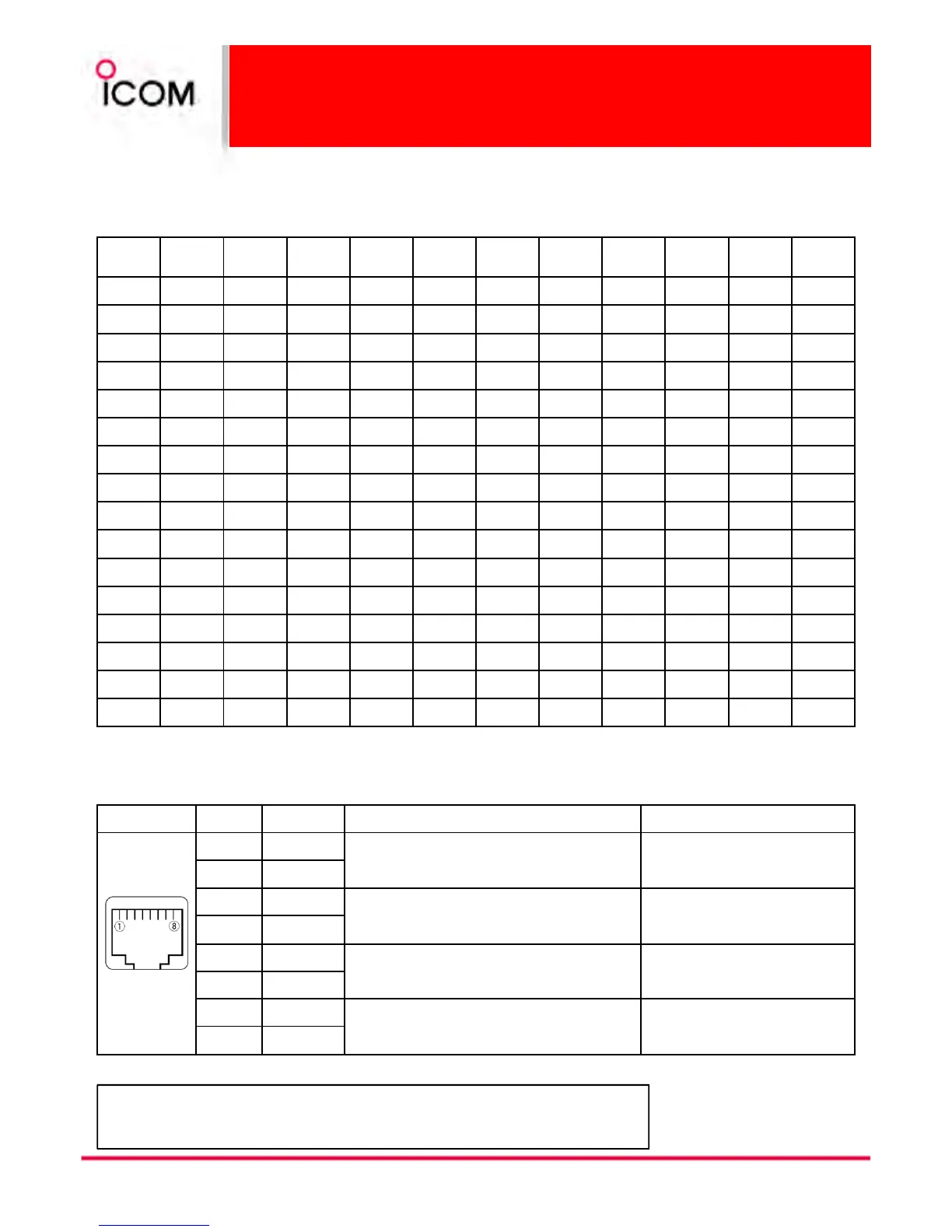
Pin No.
Pin No.Pin No.
Pin No. Pin Name
Pin NamePin Name
Pin Name Description
DescriptionDescription
Description Specification
SpecificationSpecification
Specification
1 –PTT
Input terminals to transmit the repeater in relation
to the external equipment. An opto-isolator is
provided to facilitate PTT signals.
High voltage=PTT ON (transmits)
Hi-Z=PTT OFF
2 +PTT
3 –AFOUT
Output terminal for AF signals from the AF
detector circuit via the bandpass filter. Output
level is fixed, regardless of [AF] control.
Output impedance: 600 Ω
4 +AFOUT
5 –EXTMOD
Input terminal for the modulation circuit. Input impedance: 600 Ω
6 +EXTMOD
7 –BUSY
Output terminal for squelch condition
(Open/Close). An opto-isolator is provided to
facilitate BUSY signals.
Open collector=BUSY OFF
0 V=BUSY ON (Squelch is opened)
8 +BUSY
Remote connector
Remote connectorRemote connector
Remote connector
*About Remote connector (pins 7, 8) and Accessory connector (pin 1):
*About Remote connector (pins 7, 8) and Accessory connector (pin 1):*About Remote connector (pins 7, 8) and Accessory connector (pin 1):
*About Remote connector (pins 7, 8) and Accessory connector (pin 1):
Depends on the clone setting, BUSY signals are output while receiving a signal
with a matched CTCSS/DCS signal.
 Loading...