New2001
8
1
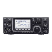
PANEL DESCRIPTION
1
!9S/RFMETER
Shows the relative signal strength of the receive sig- ➥
nal.
Shows the output power level of the transmit signal. ➥
(p. 38)
@0POWERICONS (p. 39)
“ SLO” appears when S-low power is selected. ➥
“ LO1” appears when low 1 power is selected. ➥
“ LO2” appears when low 2 power is selected. ➥
“ MID” appears when mid power is selected. ➥
No icon appears when high power is selected. ➥
@1MEMORYNAMEDISPLAY
While in the Memory mode, the programmed memory or
memory bank name is displayed.
@2 FREqUENCY READOUT
Displays a variety of information, such as the operating
frequency, menu contents and so on.
•Thedecimalpointblinksduringascan.
@3MAINBANDICON (p. 32)
Shows the selected band (A or B) is the Main band.
PANEL DESCRIPTION

 Loading...