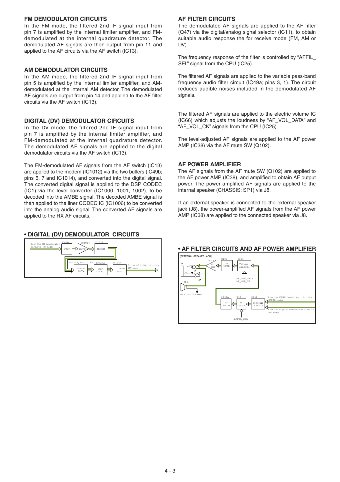
• DIGITAL (DV) DEMODULATOR CIRCUITS
• AF FILTER CIRCUITS AND AF POWER AMPLIFIER
4 - 3
BUFF
BUFF
IC49b
To the AF filter circuits
(DV mode)
From the FM demodulator
circuits (DV mode)
CNV.
CODEC
LEVEL
IC1014
LINEAR
IC1013
IC1006
MODEM
IC1012
CODEC
DSP
IC1000,1001,1002
AF
AM P
SP1
Internal speaker
J8
[EXTERNAL SPEAKER JACK]
Volume
control
IC38
Q102
IC66
MUTE
SP
SELECT
DIGI/AN
AF
FILTER
AF
FILTER
IC11Q47IC49a
From the FM/AM demodulator circuits
(FM/AM mode)
From the digital demodulator circuits
(DV mode)
AF_VOL_DATA
AF_VOL_CK
AFFIL_SEL
FM DEMODULATOR CIRCUITS
In the FM mode, the filtered 2nd IF signal input from
pin 7 is amplified by the internal limiter amplifier, and FM-
demodulated at the internal quadrature detector. The
demodulated AF signals are then output from pin 11 and
applied to the AF circuits via the AF switch (IC13).
AM DEMODULATOR CIRCUITS
In the AM mode, the filtered 2nd IF signal input from
pin 5 is amplified by the internal limiter amplifier, and AM-
demodulated at the internal AM detector. The demodulated
AF signals are output from pin 14 and applied to the AF fi lter
circuits via the AF switch (IC13).
DIGITAL (DV) DEMODULATOR CIRCUITS
In the DV mode, the filtered 2nd IF signal input from
pin 7 is amplified by the internal limiter amplifier, and
FM-demodulated at the internal quadrature detector.
The demodulated AF signals are applied to the digital
demodulator circuits via the AF switch (IC13).
The FM-demodulated AF signals from the AF switch (IC13)
are applied to the modem (IC1012) via the two buffers (IC49b;
pins 6, 7 and IC1014), and converted into the digital signal.
The converted digital signal is applied to the DSP CODEC
(IC1) via the level converter (IC1000, 1001, 1002), to be
decoded into the AMBE signal. The decoded AMBE signal is
then applied to the liner CODEC IC (IC1006) to be converted
into the analog audio signal. The converted AF signals are
applied to the RX AF circuits.
AF FILTER CIRCUITS
The demodulated AF signals are applied to the AF filter
(Q47) via the digital/analog signal selector (IC11), to obtain
suitable audio response the for receive mode (FM, AM or
DV).
The frequency response of the fi lter is controlled by “AFFIL_
SEL” signal from the CPU (IC25).
The fi ltered AF signals are applied to the variable pass-band
frequency audio filter circuit (IC49a; pins 3, 1). The circuit
reduces audible noises included in the demodulated AF
signals.
The fi ltered AF signals are applied to the electric volume IC
(IC66) which adjusts the loudness by “AF_VOL_DATA” and
“AF_VOL_CK” signals from the CPU (IC25).
The level-adjusted AF signals are applied to the AF power
AMP (IC38) via the AF mute SW (Q102).
AF POWER AMPLIFIER
The AF signals from the AF mute SW (Q102) are applied to
the AF power AMP (IC38), and amplifi ed to obtain AF output
power. The power-amplified AF signals are applied to the
internal speaker (CHASSIS; SP1) via J8.
If an external speaker is connected to the external speaker
jack (J8), the power-amplifi ed AF signals from the AF power
AMP (IC38) are applied to the connected speaker via J8.

 Loading...


