4 - 4
LO
AMP
D/A
BUFF
BUFF
AMP
VCO
SW
VCO
SW
MUTE
Q109
Q111
D145-148
Q73
D87,91,92
Q76
From the TX AF
circuits (FM mode)
From the digital converter
circuits (DV mode)
IC48c
MOD
MOD
MOD
MUTE
Q64
MUTE
IC9
IC8
IC45
To the TX amplifer
circuits
D102
Q113
D160,D175
VHF VCO
UHF VCO
Digi/Ana
line SW
IC34
From the TX AF
circuits
To the modulation circuits
BUFF
CNV.
CODEC
LEVEL
IC1014
BUFF
IC1015
LINEAR
IC1012
IC1006
MODEM
IC1013
CODEC
DSP
IC1000,1001,1002
MIC
MUT E
Pre-emphasis
and IDC
SPLATTER
MIC
AM P
J2
1
2
3
4
5
6
7
8
ALC
AM P
HPF
MIC
IC48d
SW
MIC GAIN
SWITCH
DA_SEL
AF
IC51
IC32
AF
SW
IC28
IC30
AF
IC29 IC52
SW
Q88
IC48b
Q87
From the microphone
To the modulation circuits
(FM mode)
To the digital converter circuits
(DV mode)
Level
ADJ.
IC48a
4-2 TRANSMITTER CIRCUITS
TX AF CIRCUITS
MIC signals from the connected microphone are passed
through the HPF (Q87), and amplified by the MIC AMP
(IC28). The amplified MIC signals are passed through the
MIC gain SW (Q88) which selects the MIC sensitivity from
“High” or “Low,” and the MIC mute SW (IC30), then passed
through or bypassed the ALC AMP (IC32) via the AF SWs
(IC29 and IC52).
In the DV mode, the MIC signals are applied to the ALC
AMP (IC32) which automatically adjusts the level of MIC
signals for digital processing,
The MIC signals from the AF SW (IC52) are passed through
the pre-emphasis and IDC (for amplitude-limitting) circuits
(IC48b), MIC level adjustment circuit (IC48a) and the
splatter circuit (IC48d) which cuts off the 3 kHz and higher
audio signals. The filtered MIC signals are applied to the
modulation circuits via the AF SW (IC51; pins 1, 7).
In the DV mode, the filtered MIC signals are applied to
the digital converter circuits before being applied to the
modulation circuits via the AF SW (IC51; pins 1, 6).
DIGITAL CONVERTER CIRCUITS
The MIC signals from the TX AF circuits are applied to
the liner CODEC IC (IC1013) via the buffer (IC1014), and
encoded into the digital audio signal. The encoded digital
audio signal is then applied to the DSP CODEC IC (IC1006)
and converted into the AMBE signal. The AMBE signal
is applied to the modem (IC1012) via the level converter
(IC1000, 1001,1002). The modem IC converts the AMBE
signal into the analog signal, and output to the modulation
circuits via the buffer (IC1015) and the digital/analog line SW
(IC34).
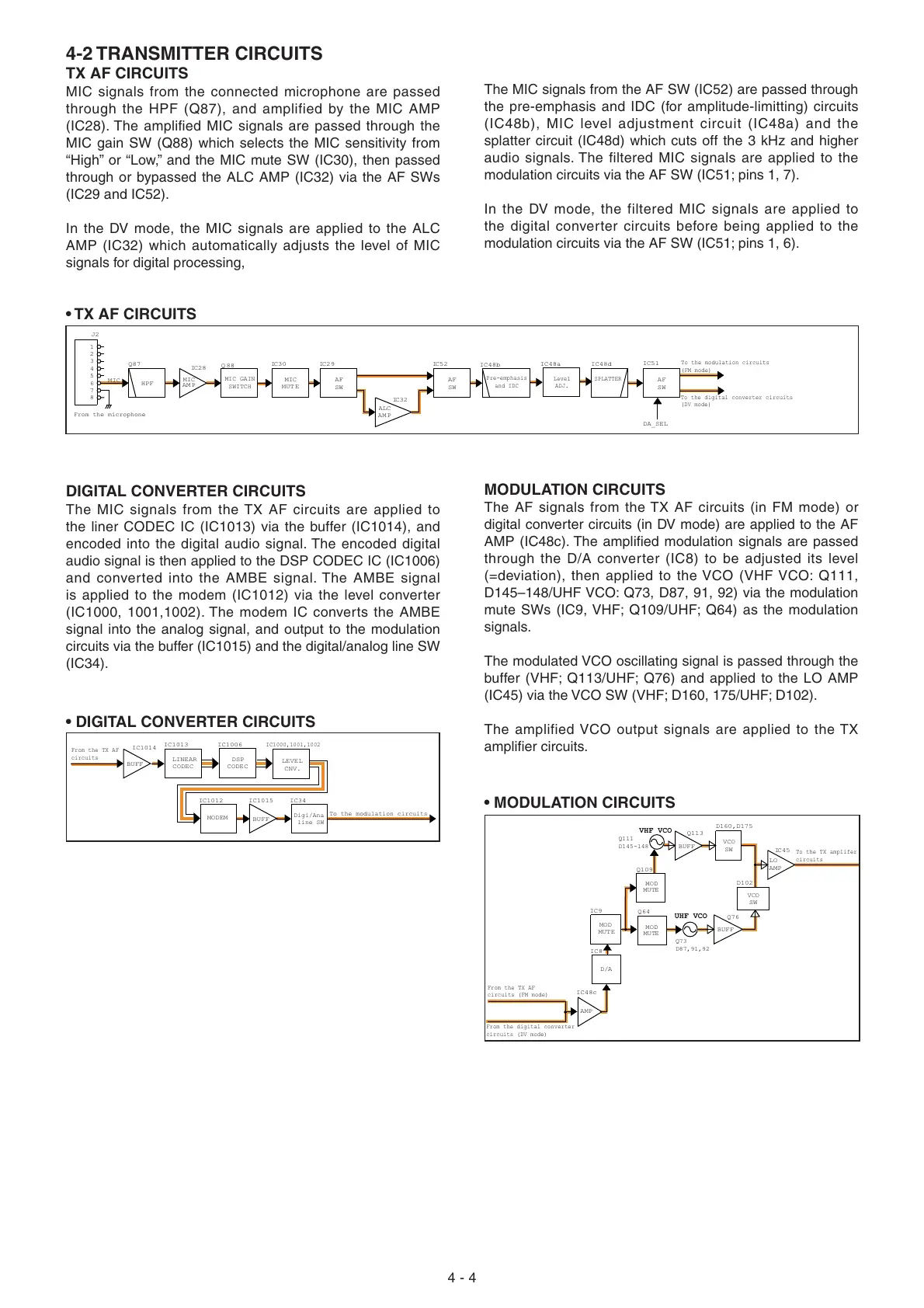
MODULATION CIRCUITS
The AF signals from the TX AF circuits (in FM mode) or
digital converter circuits (in DV mode) are applied to the AF
AMP (IC48c). The amplifi ed modulation signals are passed
through the D/A converter (IC8) to be adjusted its level
(=deviation), then applied to the VCO (VHF VCO: Q111,
D145–148/UHF VCO: Q73, D87, 91, 92) via the modulation
mute SWs (IC9, VHF; Q109/UHF; Q64) as the modulation
signals.
The modulated VCO oscillating signal is passed through the
buffer (VHF; Q113/UHF; Q76) and applied to the LO AMP
(IC45) via the VCO SW (VHF; D160, 175/UHF; D102).
The amplified VCO output signals are applied to the TX
amplifi er circuits.
• TX AF CIRCUITS
• MODULATION CIRCUITS
• DIGITAL CONVERTER CIRCUITS

 Loading...


