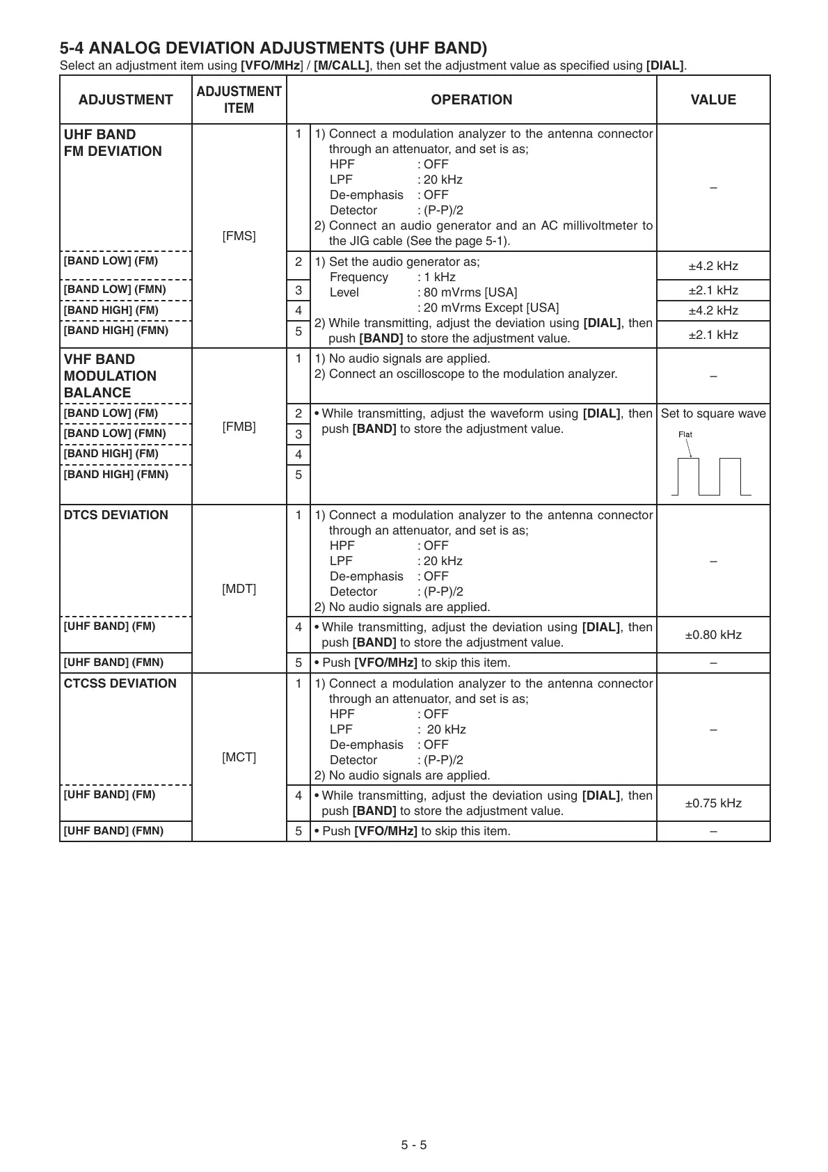
5-4 ANALOG DEVIATION ADJUSTMENTS (UHF BAND)
Select an adjustment item using [VFO/MHz] / [M/CALL], then set the adjustment value as specifi ed using [DIAL].
ADJUSTMENT
ADJUSTMENT
ITEM
OPERATION VALUE
UHF BAND
FM DEVIATION
[FMS]
1 1) Connect a modulation analyzer to the antenna connector
through an attenuator, and set is as;
HPF : OFF
LPF : 20 kHz
De-emphasis : OFF
Detector : (P-P)/2
2) Connect an audio generator and an AC millivoltmeter to
the JIG cable
(See the page 5-1)
.
–
[BAND LOW] (FM)
2 1) Set the audio generator as;
Frequency : 1 kHz
Level : 80 mVrms [USA]
: 20 mVrms Except [USA]
2) While transmitting, adjust the deviation using [DIAL], then
push [BAND] to store the adjustment value.
±4.2 kHz
[BAND LOW] (FMN)
3 ±2.1 kHz
[BAND HIGH] (FM)
4 ±4.2 kHz
[BAND HIGH] (FMN)
5
±2.1 kHz
VHF BAND
MODULATION
BALANCE
[FMB]
1 1) No audio signals are applied.
2) Connect an oscilloscope to the modulation analyzer.
–
[BAND LOW] (FM)
2• While transmitting, adjust the waveform using [DIAL], then
push [BAND] to store the adjustment value.
Set to square wave
[BAND LOW] (FMN)
3
[BAND HIGH] (FM)
4
[BAND HIGH] (FMN)
5
DTCS DEVIATION
[MDT]
1 1) Connect a modulation analyzer to the antenna connector
through an attenuator, and set is as;
HPF : OFF
LPF : 20 kHz
De-emphasis : OFF
Detector : (P-P)/2
2) No audio signals are applied.
–
[UHF BAND] (FM)
4• While transmitting, adjust the deviation using [DIAL], then
push [BAND] to store the adjustment value.
±0.80 kHz
[UHF BAND] (FMN)
5• Push [VFO/MHz] to skip this item. –
CTCSS DEVIATION
[MCT]
1 1) Connect a modulation analyzer to the antenna connector
through an attenuator, and set is as;
HPF : OFF
LPF : 20 kHz
De-emphasis : OFF
Detector : (P-P)/2
2) No audio signals are applied.
–
[UHF BAND] (FM)
4• While transmitting, adjust the deviation using [DIAL], then
push [BAND] to store the adjustment value.
±0.75 kHz
[UHF BAND] (FMN)
5• Push [VFO/MHz] to skip this item. –
5 - 5

 Loading...


