5 - 2
(See the page 5-1)
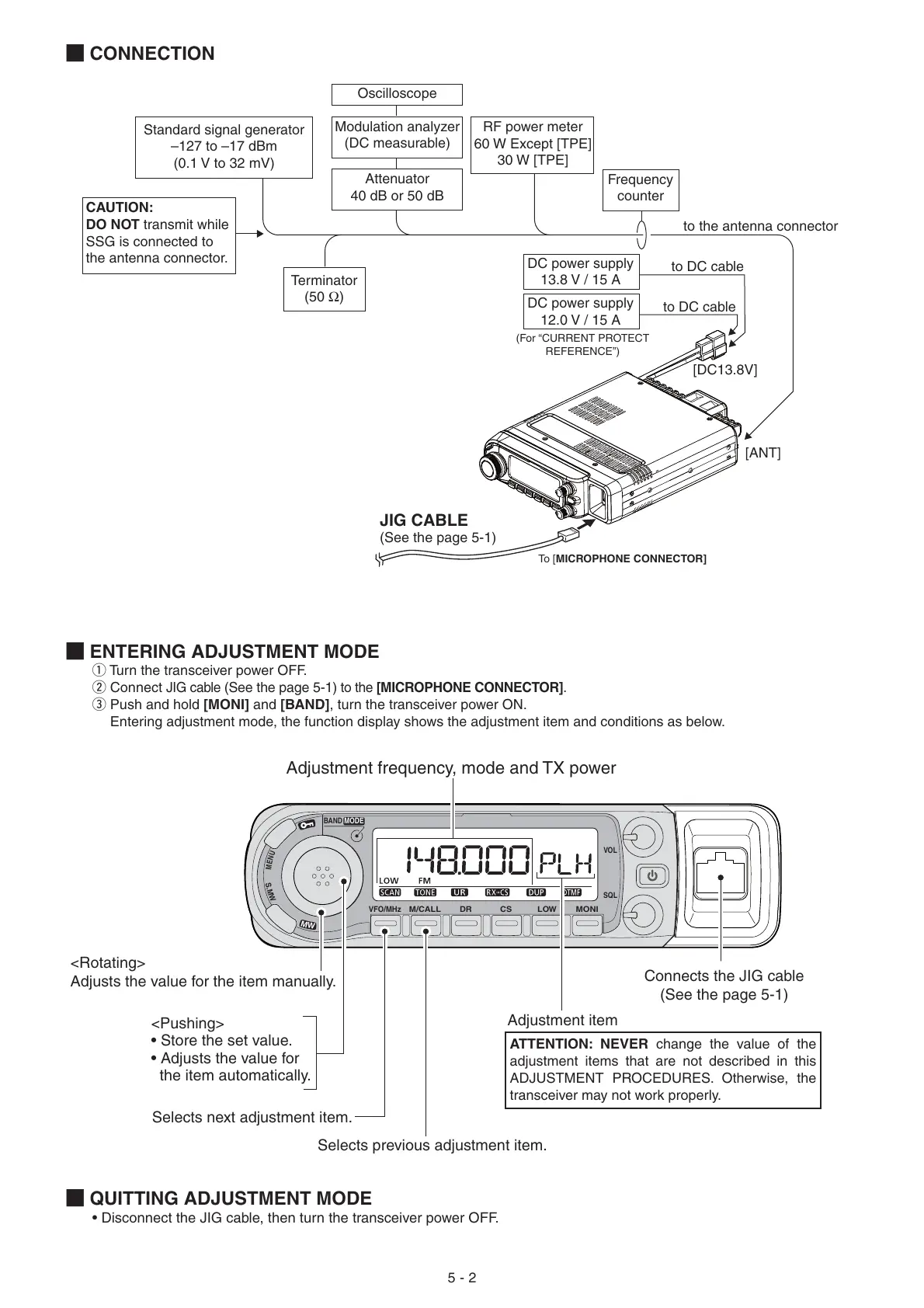
JIG CABLE
Modulation analyzer
(DC measurable)
Attenuator
40 dB or 50 dB
to the antenna connector
to DC cable
[ANT]
[DC13.8V]
Standard signal generator
–127 to –17 dBm
(0.1 V to 32 mV)
CAUTION:
DO NOT transmit while
SSG is connected to
the antenna connector.
RF power meter
60 W Except [TPE]
30 W [TPE]
DC power supply
13.8 V / 15 A
(For “CURRENT PROTECT
REFERENCE”)
Frequency
counter
to DC cable
DC power supply
12.0 V / 15 A
Oscilloscope
Terminator
(50 Ω)
To [ MICROPHONE CONNECTOR]
M ENTERING ADJUSTMENT MODE
q Turn the transceiver power OFF.
w Connect
JIG cable
(See the page 5-1)
to the [MICROPHONE CONNECTOR].
e Push and hold [MONI] and [BAND], turn the transceiver power ON.
Entering adjustment mode, the function display shows the adjustment item and conditions as below.
M
QUITTING ADJUSTMENT MODE
• Disconnect the JIG cable, then turn the transceiver power OFF.
M
CONNECTION
VFO/MHz
BAND
MODE
VOL
SQL
M/CALL CSDR LOW
MONI
S
.
M
W
M
W
M
E
N
U
Adjustment frequency, mode and TX power
Selects next adjustment item.
Selects previous adjustment item.
<Rotating>
Adjusts the value for the item manually.
Connects the JIG cable
(See the page 5-1)
Adjustment item
<Pushing>
• Store the set value.
• Adjusts the value for
the item automatically.
ATTENTION: NEVER change the value of the
adjustment items that are not described in this
ADJUSTMENT PROCEDURES. Otherwise, the
transceiver may not work properly.

 Loading...


