4 - 2
• 2ND IF CIRCUITS
X3
BPF
CERAMIC
X2
PLL
IC
BPF
CERAMIC
Q52
IC14
FI2
WIDE/NARROW
SELECTOR
IC15
IF IC
(For narrow)
450 kHz 2nd IF filter
(For wide)
FI1
DETECT
SIGNAL
SELECTOR
TCXO
15.3 MHz
X5
IC13
2nd LO
Pin 11(FM/DV mode)
Pin 14(AM mode)
45.9 MHz
From the 1st IF circuits
To the AF filter circuits
(FM/AM mode)
To the digital demodulator circuits
(DV mode)
IF
AM P BPF
XTAL
140_LO
440_LO
UHF_L O
Q66
46.35MHz
FI6
From the 140 MHz band
RF circuit
From the 440 MHz band
RF circuit
To the 2nd IF
circuits
From the 300 MHz and
800 MHz bands RF circuit
D88
LIMIT
Q124
Q125
LIMIT
D1009
IC64
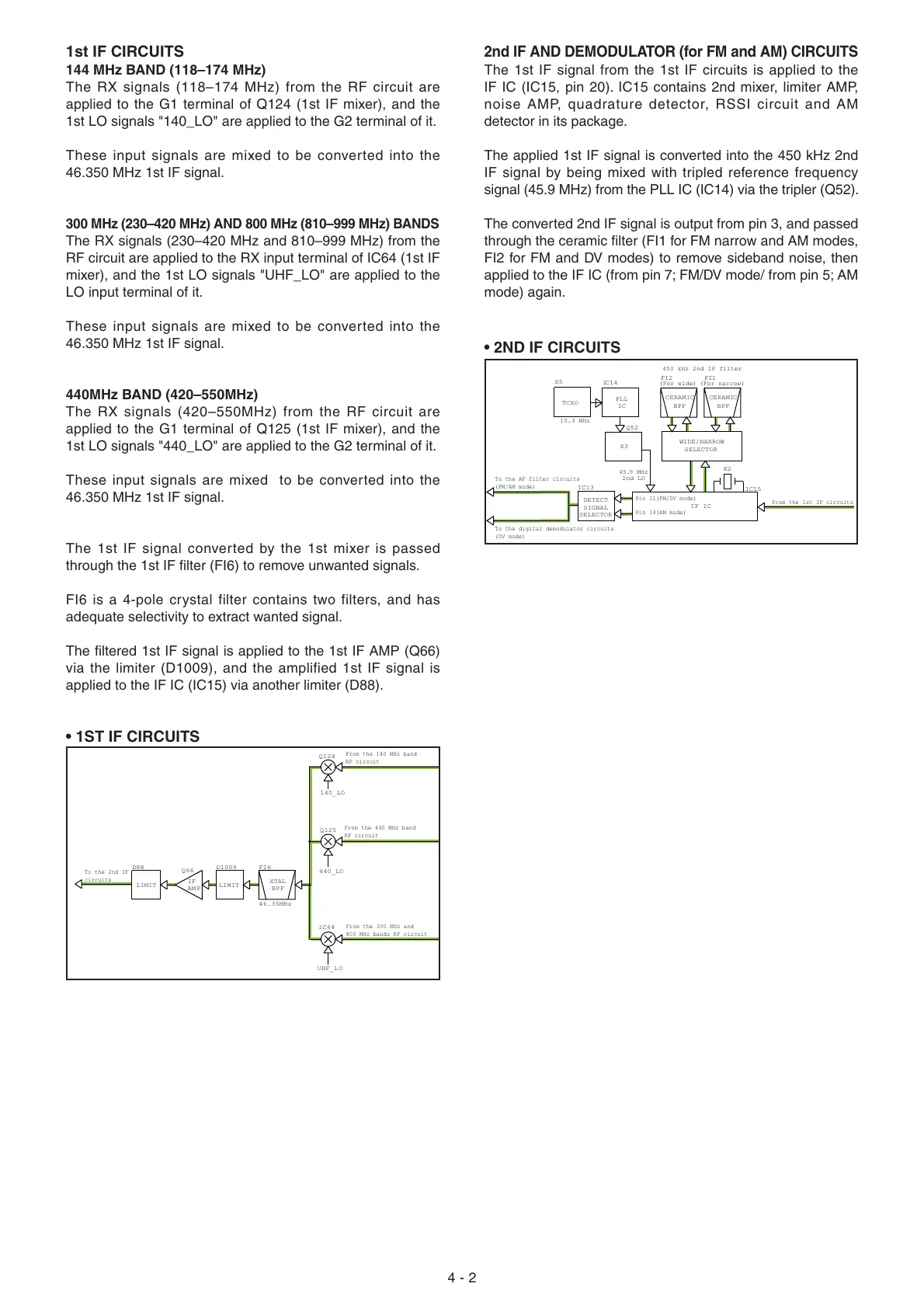
2nd IF AND DEMODULATOR (for FM and AM) CIRCUITS
The 1st IF signal from the 1st IF circuits is applied to the
IF IC (IC15, pin 20). IC15 contains 2nd mixer, limiter AMP,
noise AMP, quadrature detector, RSSI circuit and AM
detector in its package.
The applied 1st IF signal is converted into the 450 kHz 2nd
IF signal by being mixed with tripled reference frequency
signal (45.9 MHz) from the PLL IC (IC14) via the tripler (Q52).
The converted 2nd IF signal is output from pin 3, and passed
through the ceramic fi lter (FI1 for FM narrow and AM modes,
FI2 for FM and DV modes) to remove sideband noise, then
applied to the IF IC (from pin 7; FM/DV mode/ from pin 5; AM
mode) again.
1st IF CIRCUITS
144 MHz BAND (118–174 MHz)
The RX signals (118–174 MHz) from the RF circuit are
applied to the G1 terminal of Q124 (1st IF mixer), and the
1st LO signals "140_LO" are applied to the G2 terminal of it.
These input signals are mixed to be converted into the
46.350 MHz 1st IF signal.
300 MHz (230–420 MHz) AND 800 MHz (810–999 MHz) BANDS
The RX signals (230–420 MHz and 810–999 MHz) from the
RF circuit are applied to the RX input terminal of IC64 (1st IF
mixer), and the 1st LO signals "UHF_LO" are applied to the
LO input terminal of it.
These input signals are mixed to be converted into the
46.350 MHz 1st IF signal.
440MHz BAND (420–550MHz)
The RX signals (420–550MHz) from the RF circuit are
applied to the G1 terminal of Q125 (1st IF mixer), and the
1st LO signals "440_LO" are applied to the G2 terminal of it.
These input signals are mixed to be converted into the
46.350 MHz 1st IF signal.
The 1st IF signal converted by the 1st mixer is passed
through the 1st IF fi lter (FI6) to remove unwanted signals.
FI6 is a 4-pole crystal filter contains two filters, and has
adequate selectivity to extract wanted signal.
The fi ltered 1st IF signal is applied to the 1st IF AMP (Q66)
via the limiter (D1009), and the amplified 1st IF signal is
applied to the IF IC (IC15) via another limiter (D88).
• 1ST IF CIRCUITS

 Loading...


