Detailed Function Description
101
6.13 PC Group --Serial Communication
For details, please refer to operation manual of serial communication card.
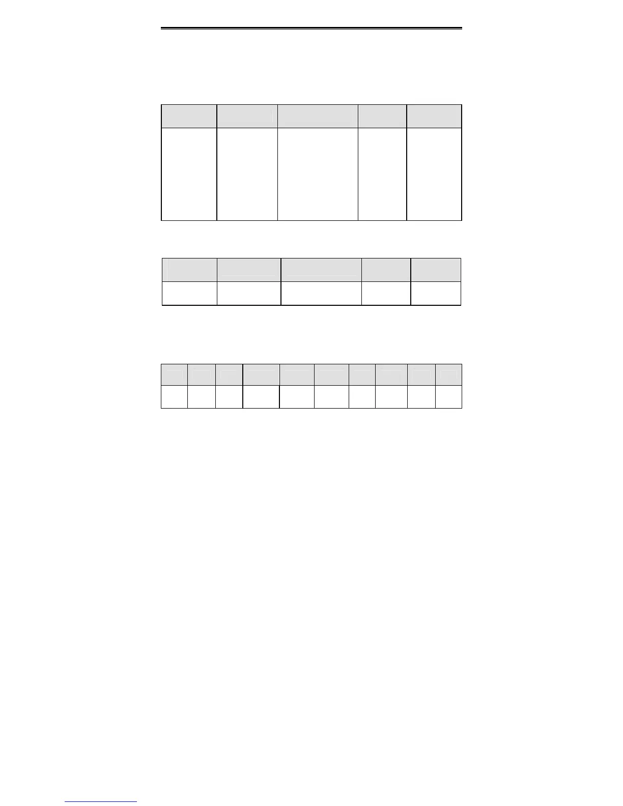
6.14 PD Group --Supplementary Function
Function
Code
Name Description
Setting
Range
Factory
Setting
PD.00
Upper
frequency limit
selection
0: Keypad
1: AI1
2: AI2
3: AI3
4: AI4
5: HDI 1
6: HDI 2
7: communication
0~7 0
0: Keypad: User can set the value of P0.08 as upper frequency limit.
1~7: Please refer to description of P0.03.
Function
Code
Name Description
Setting
Range
Factory
Setting
PD.01
NO/NC input
selection
0~0x3FF 0~0x3FF 0
This parameter determines NO or NC status of each input terminal. It is a hexadecimal
value. If the corresponding bit is set to be 1, that means this input terminal is
normal-close (NC) input. Please refer to following table.
BIT9 BIT8 BIT7 BIT6 BIT5 BIT4 BIT3 BIT2 BIT1 BIT0
S8 S7 S6 HDI2 HDI1 S5 S4 S3 S2 S1
Notice: Only when HDI1 or HDI2 is set to be ON-OFF input, the setting of bit 5 or bit
6 will take effect.
6.15 PE Group –Factory Setting
This group is the factory-set parameter group. It is prohibited for user to access.
 Loading...
