Wiring
25
be installed at the input side. It can also prevent rectifier from sudden variation of power
voltage or harmonic generated by phase-control load.
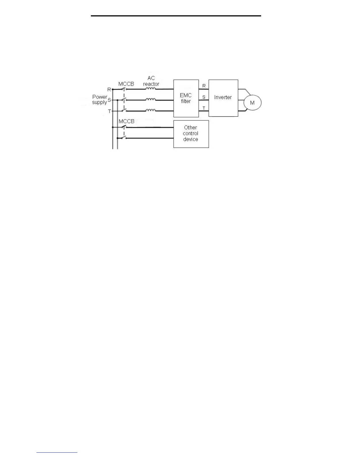
z Input EMC filter
The surrounding device may be disturbed by the cables when the inverter is working.
EMC filter can minimize the interference. Just like the following figure.
Figure4.9 Wiring at input side.
4.5.2 Wiring for inverter
z DC reactor
Inverters from 18.5kW to 90kW have built-in DC reactor which can improve the power
factor,
z Braking unit and braking resistor
• Inverters of 15KW and below have built-in braking unit. In order to dissipate the
regenerative energy generated by dynamic braking, the braking resistor should be
installed at (+) and PB terminals. The wire length of braking resistor should be less than
5m.
• Inverter of 18.5KW and above need connect external braking unit which should be
installed at (+) and (-) terminals. The cable between inverter and braking unit should be
less than 5m. The cable between braking unit and braking resistor should be less than
10m.
• The temperature of braking resistor will increase because the regenerative energy will
be transformed to heat. Safety protection and good ventilation is recommended.
 Loading...
