Detailed Function Description
78
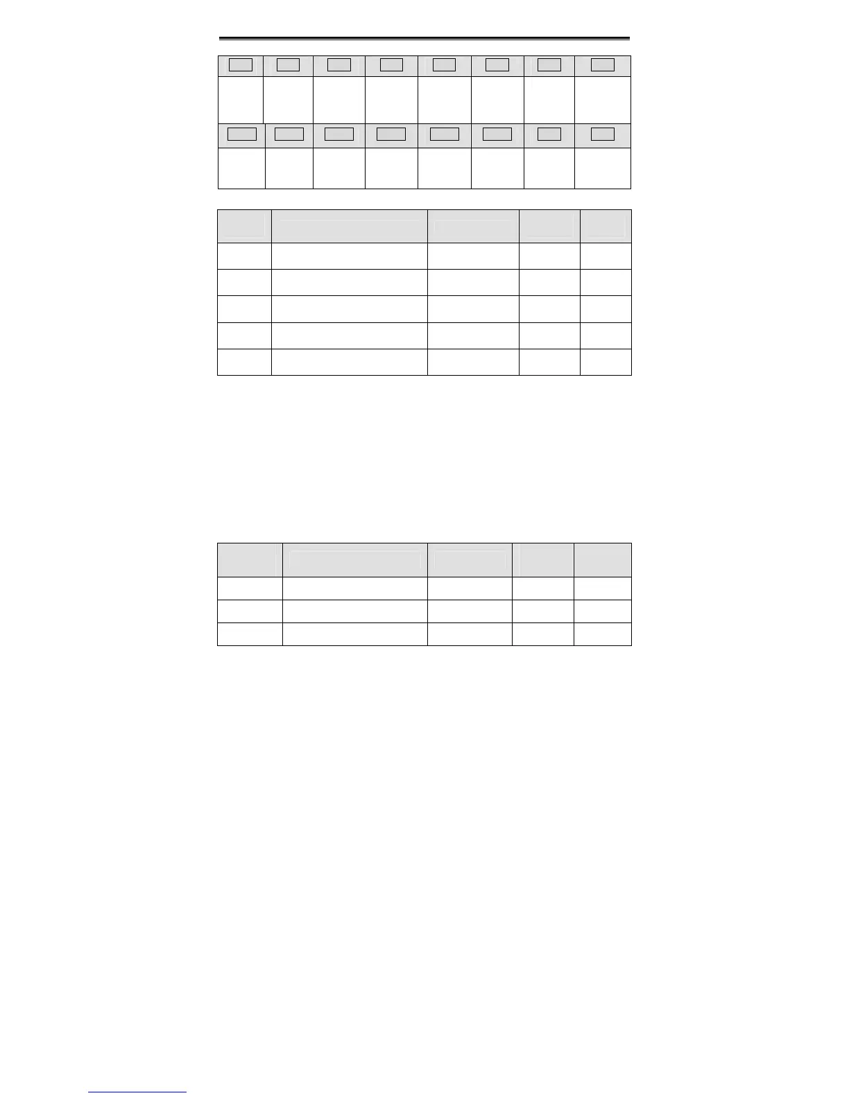
BIT7 BIT6 BIT5 BIT4 BIT3 BIT2 BIT1 BIT0
AI2 AI1
PID
feedback
PID preset
Output
terminal
status
Input
terminal
status
DC bus
voltage
Reference
frequency
BIT15 BIT14 BIT13 BIT12 BIT11 BIT10 BIT9 BIT8
Reserved Reserved
Length
value
Step No. o
PLC or
multi-step
HDI2
frequency
HDI1
frequency
AI4 AI3
Function
Code
Name Description
Setting
Range
Factory
Setting
P7.08
Rectifier module temperature
0~100.0℃
P7.09
IGBT module temperature
0~100.0℃
P7.10
MCU software version
P7.11
DSP software version
P7.12
Accumulated running time 0~65535h
Rectifier module temperature: Indicates the temperature of rectifier module. Overheat
protection point of different inverter may be different.
IGBT module temperature: Indicates the temperature of IGBT module. Overheat
protection point of different inverter may be different.
MCU Software version: Indicates current software version of MCU.
DSP Software version: Indicates current software version of DSP
Accumulated running time: Displays accumulated running time of inverter.
Notice: Above parameters are read only.
Function
Code
Name Description
Setting
Range
Factory
Setting
P7.13 Third latest fault type 0~30 0~30
P7.14 Second latest fault type 0~30 0~30
P7.15 Latest fault type 0~30 0~30
These parameters record three recent fault types. For details, please refer to description
of chapter 7.
 Loading...
