ARMY TM 9-2815-254-24
AIR FORCE TO 36G1-94-2
h.
After hot plug has been removed, use hammer and same brass bar through hot plug hole to lightly tap lower
side of heat shield (14) and drive it free. Remove heat shield (14) and washer (15).
i.
Remove valve guides (16) using a hammer and valve guide replacer (NU-7634) to drive out guides from lower
face of cylinder heed.
j.
Remove valve seat inserts (17 and 18) as follows:
(1) Using MIG welder (refer to TM 9-239) weld four spots evenly spaced to inside circumference of valve
seat insert. These will be used to pry insert free.
(2) Allow it to cool for a few minutes which will cause contraction and make removal easier.
Use care not to damage cylinder head.
(3)
Use a screwdriver and pry valve seat insert free.
(4)
Carefully remove carbon and other foreign material from cylinder head insert bore.
3-27.3. Inspect and Measure.
a.
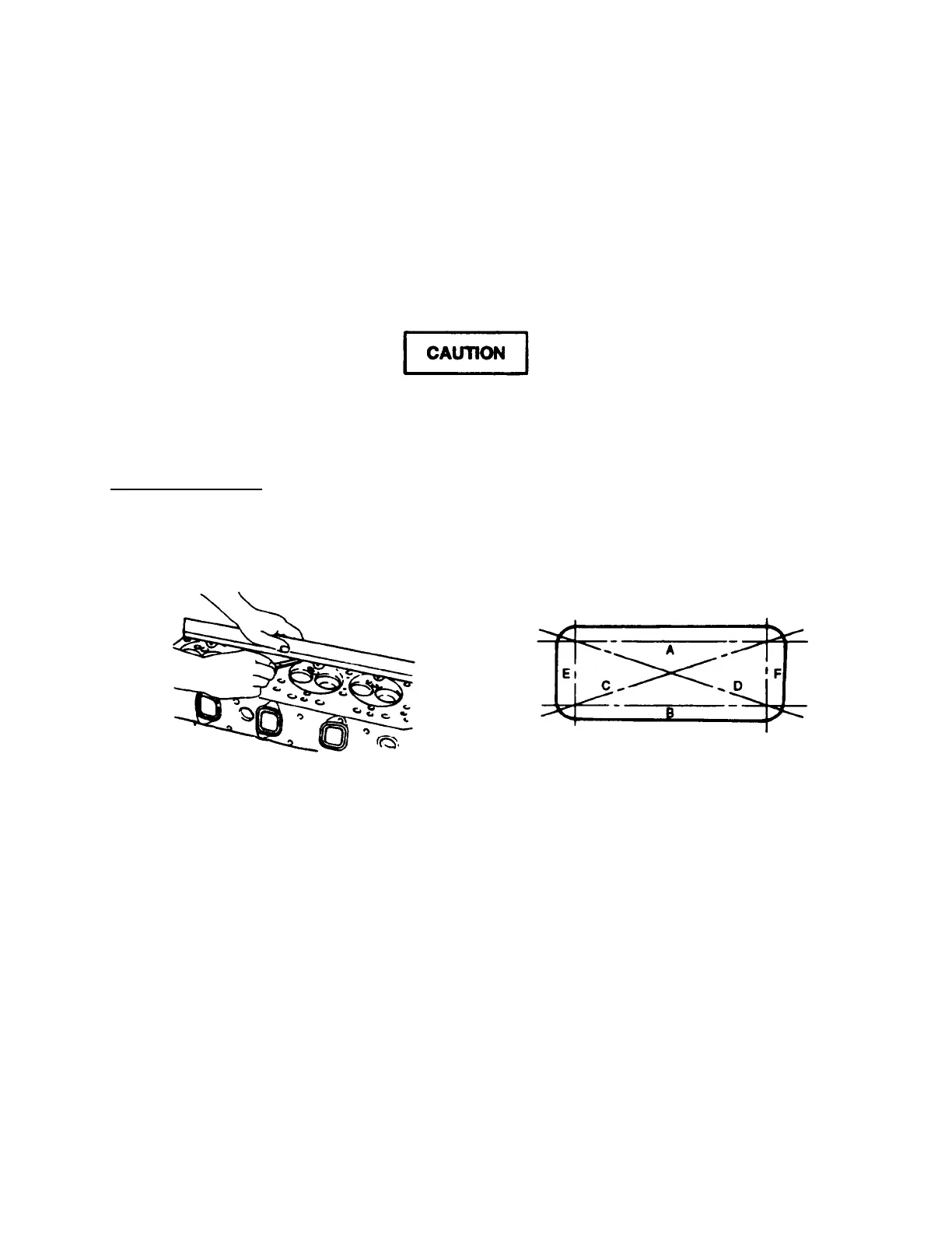
Check cylinder head lower face warpage as follows:
(1)
Use a straight edge and feeler gage to measure the four sides and two diagonals of cylinder head lower
face, refer to FIGURE 3-63.
FIGURE 3-63. Cylinder Head Inspection
3-114
 Loading...