Inspection and Installation
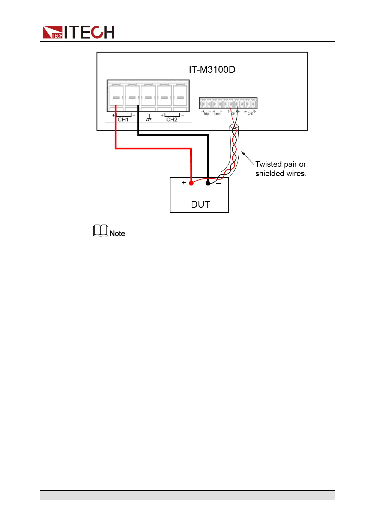
To ensure the stability of the system, use shielded twisted-pair cables be-
tween the remote sense terminals and the equipment under test.
1. Remove the output terminal cover.
2. Loosen the screws of the output terminals and connect the red and black
test cables to the output terminals, and connect the ground terminal cor-
rectly. Re-tighten the screws.
When maximum current that one test cable can withstand fails to meet the
current rated current, use multiple pieces of red and black test cables. For
example, the maximum current is 1,200 A, then 4 pieces of 360 A red and
black cables are required.
3. Refer to the wiring diagram, and use shielded twisted-pair cables to connect
the remote sense terminals and the equipment under test.
4. Thread the red and black test cables and sense cables through the output
terminals cover and install the cover.
5. Connect the other end of the remote sense cables and the red and black ca-
bles to the DUT. The positive and negative poles must be properly con-
nected and fastened when wiring.
6. Power on the instrument and turn the sense function on. Please refer to
4.1.3 Set the Sense Function State for the detailed operations.
2.7 Connect the Communication Interface
This series power supply has no standard-equipped communication interfaces.
Users can purchase communication cards separately. Users can choose one of
Copyright © Itech Electronic Co., Ltd.
23

 Loading...


