Inspection and Installation
• PC and power supply must have the same baud rate.
• Ensure you have used the correct communication cable. Please pay atten-
tion that some cable may not have a correct internal wiring even it is with an
appropriate interface.
• The cable must be connected to the correct serial ports (COM1, COM2, etc)
of PC.
2.7.6 RS-485 Interface
When the optional interface card is a DB25 analog interface (IT-E1208) with
RS-485 interface, you can quickly understand the steps required to connect the
RS-485 interface.
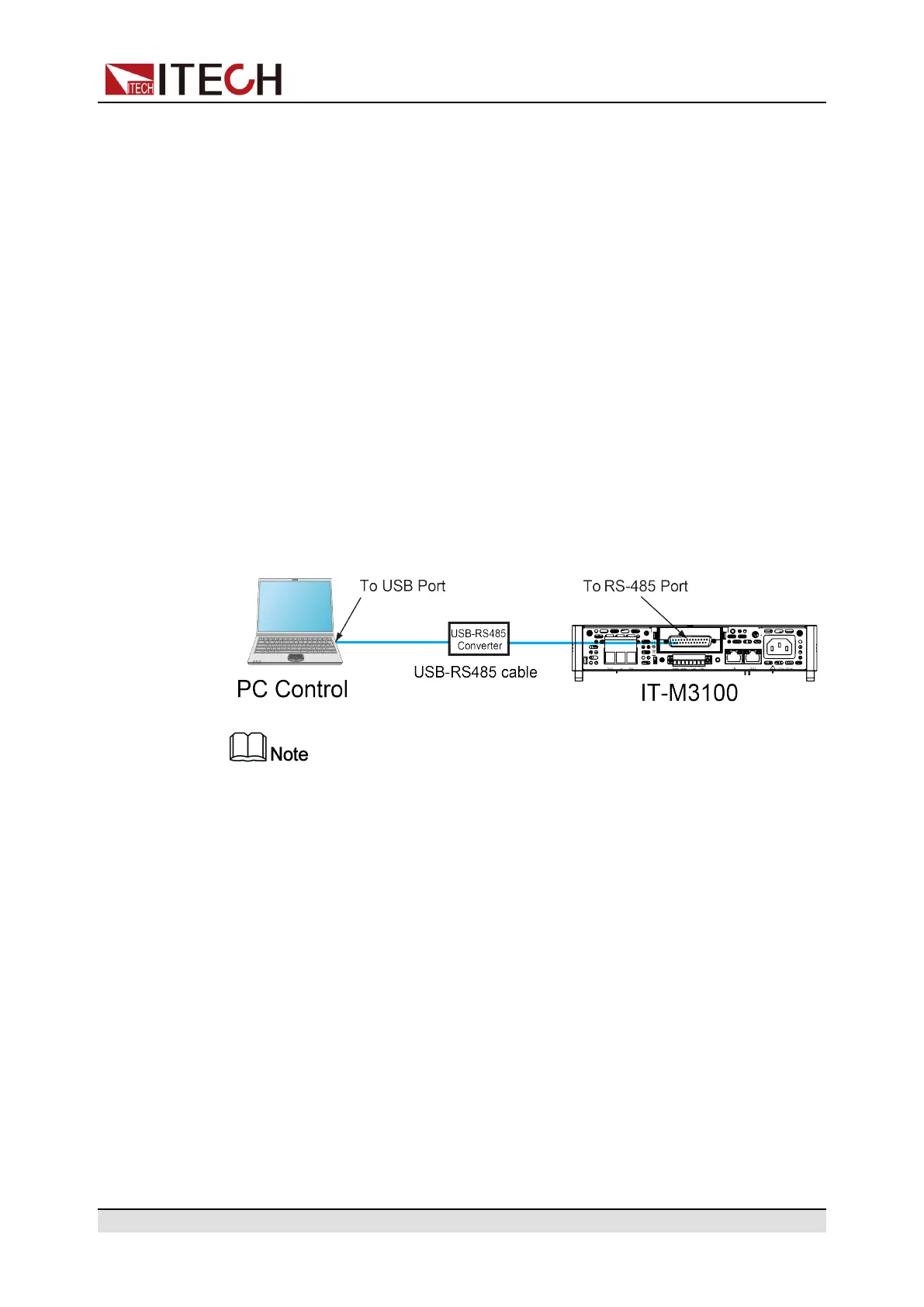
The following figure shows a typical RS-485 interface system. Users can select
the RS-485 interface converter to connect to your computer according to the ac-
tual situation, for example: RS-485 to RS-232 interface device or RS-485 to
USB interface device Etc., the RS-485 to USB interface device is taken as an
example.
The rear panel shown in the figure is only an example. The actual appear-
ance of the rear panel is subject to the specific instrument.
Definition of RS-485 Pins
RS-485 interface pins are integrated in the DB25 analog interface. Pin25 and
Pin13 are the A and B pins for RS-485. Refer to Analog interface for more
information.
RS-485 Configuration
The user needs to configure the RS-485 interface parameters in the system
menu before using the remote control. The RS-485 interface parameters are as
follows.
Copyright © Itech Electronic Co., Ltd.
37

 Loading...


