Functions and Features
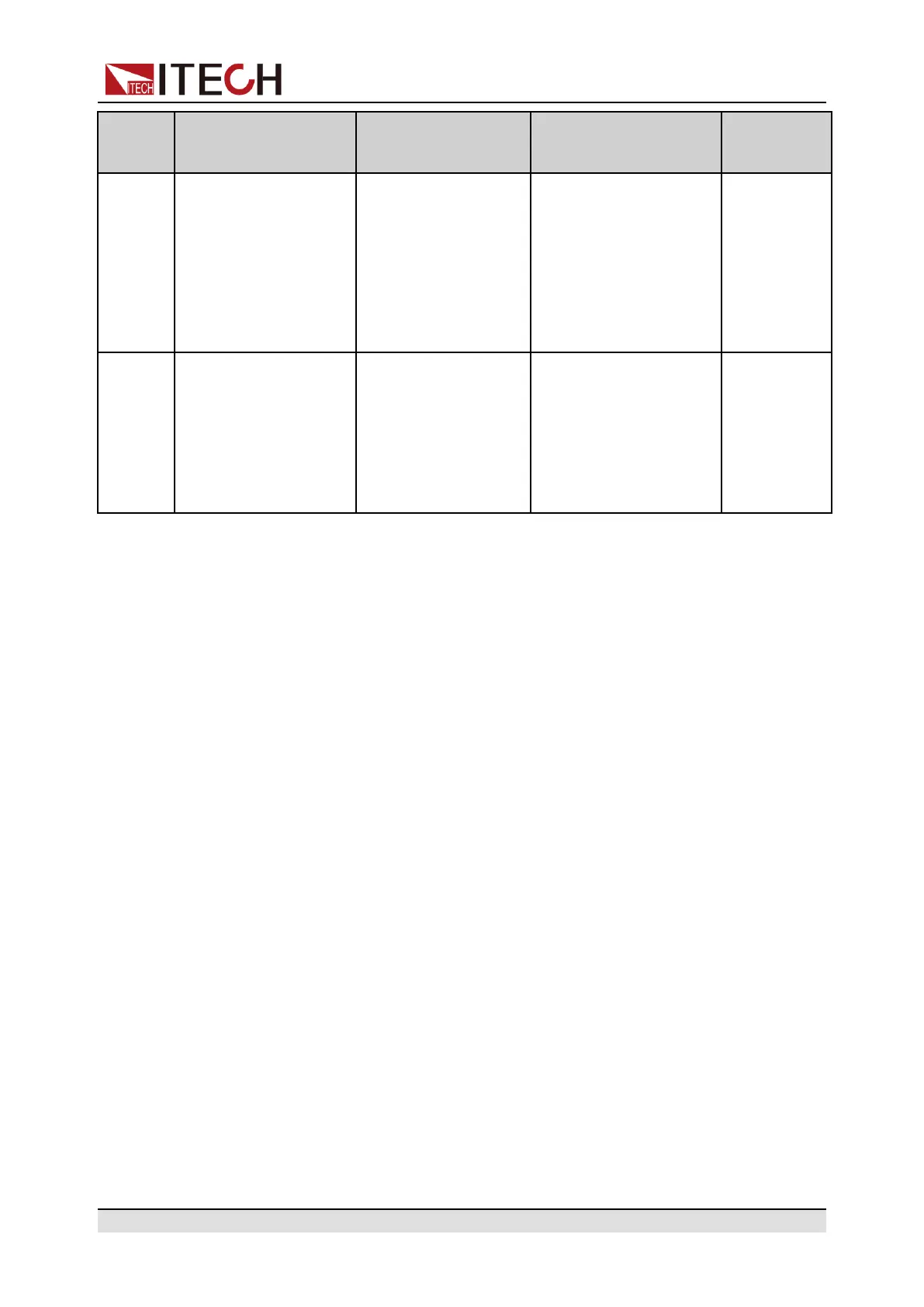
Type
Introduction
Maximum Quantity
Model Restriction
Communi-
cation
Object
Multi-
channel
Only can be used in
the PC software
(IT9000). By commu-
nicating one unit in
the System Bus link
with the PC, it is pos-
sible to independently
control any other unit
in the PC software.
A maximum of 8
units can be con-
nected in each Sys-
tem Bus link.
Multi-channel systems
can be composed of
single units of the
same series and differ-
ent models.
Any unit in
each Sys-
tem Bus link
Syn-
chroni-
zation
By operating one unit
in the System Bus link
locally or remotely, it
is possible to syn-
chronously control the
On/Off and equal-
scale output of the
other units.
A maximum of 8
units can be con-
nected in each Sys-
tem Bus link.
Synchronization sys-
tems can be composed
of single units of the
same series and differ-
ent models.
Any unit in
each Sys-
tem Bus link
4.3.1 Multi-Channel Function
When multiple power supplies are connected through the System Bus, an inde-
pendent channel number should be set for CH1 of each power supply, and the
setting items are 1, 3, 5, 7, 9, 11, 13, and 15. The Channel number of CH2 of
the same power supply will automatically increase by 1 according to the setting
of CH1. The power supply connected to the same system bus, the channel
number can not be repeated, otherwise it will cause conflicts. All power interfa-
ces will prompt “Chan Number Conflict”. In this case, rotate the knob to change
the channel number directly, press [Enter] to confirm.
After forming a multi-channel power system, the channel number is displayed
on each instrument interface. Connect the communication interface of one of
the power supplies to the PC, then the user can independently control each
power supply of the system in the PC software. The following three power sup-
plies are taken as an example to describe the connection and operation steps of
multiple channels.
Copyright © Itech Electronic Co., Ltd.
55

 Loading...


