Inspection and Installation
2.7.3 CAN Interface
When the optional interface card is RS232+CAN interface (IT-E1207), the fol-
lowing can help users quickly understand the steps required to connect to the
CAN interface.
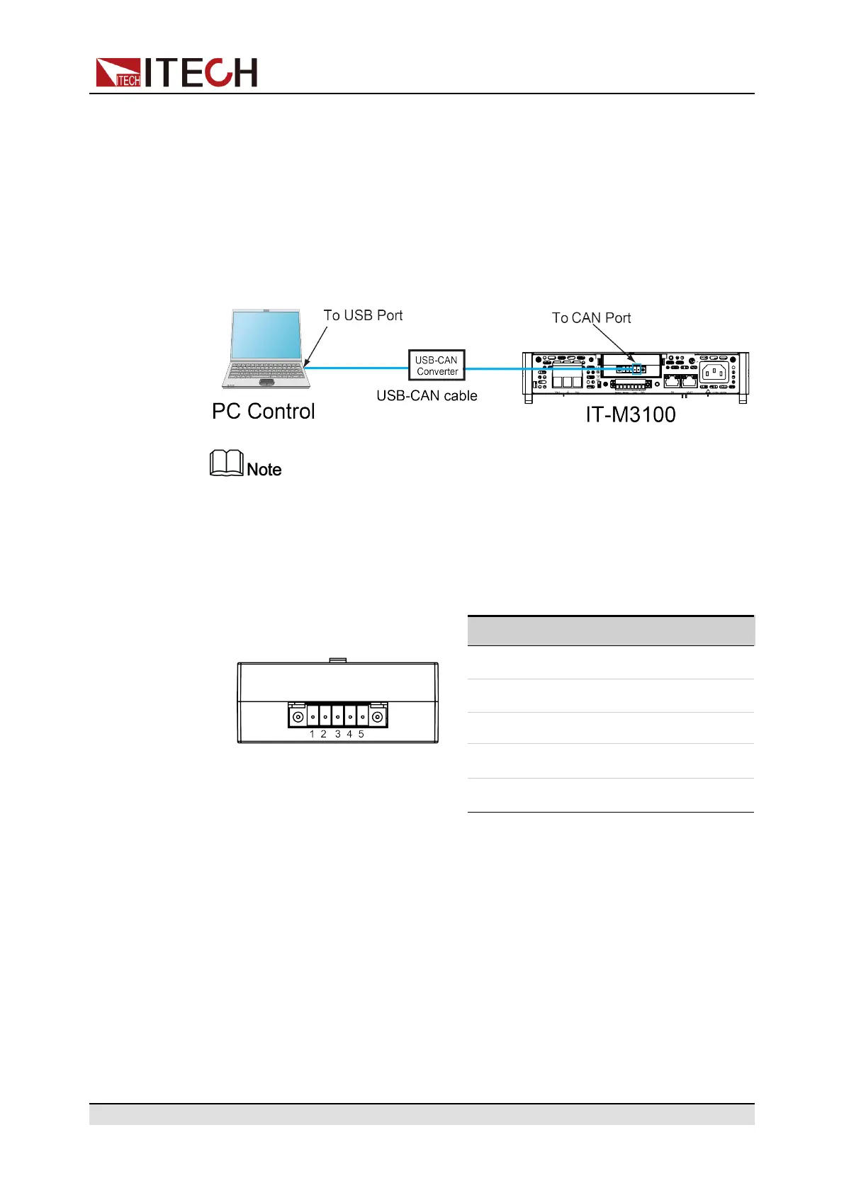
The following figure shows the CAN interface system. The user can select the
CAN interface converter to connect to your computer according to the actual sit-
uation. Take the CAN to USB interface device as an example.
The rear panel shown in the figure is only an example. The actual appear-
ance of the rear panel is subject to the specific instrument.
Definition of CAN Pins
The definition of CAN pins are as follows.
Pin Description
IT-E1207
1 TXD, transmit data
2 RXD, receive data
3 GND
4 CAN_H
5 CAN_L
CAN Configuration
The user needs to configure the CAN interface parameters in the system menu
before using the remote control. The CAN interface parameters are as follows.
Copyright © Itech Electronic Co., Ltd.
32

 Loading...


