Functions and Features
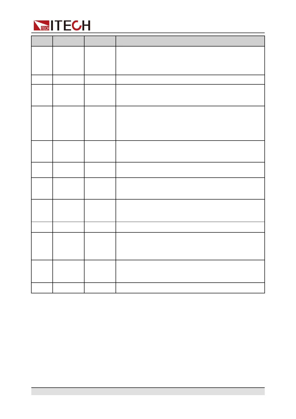
Pin Name Type Description
11 ALM Digital out Sends the signal that is used to indicate whether the power
supply malfunctions or not. When the power supply oper-
ates well, the pin generates 5 V. When the power supply
has a malfunction, the pin generates 0 V.
12 - - Not used
13, 25 RS485–A
RS485–B
Communi-
cation
interfaces
RS485 communication interfaces.
14 Vol_MON Analog out Voltage monitor signal. This pin generates a voltage of 0 V
to 10 V to monitor an output voltage of 0 V to the maximum
rated value. For example, if the maximum rated value is 80
V, and if the pin generates 2.5 V, the output voltage should
be approximately 20 V
15 Cur_Pro Analog in Programs output current. Use an input voltage in the range
of 0 V to 10 V to control the output current in the range of 0
% to 100 %.
16/17/
19
– – Not used
18 Vref Analog out Signal output for external resistance control of the DC signal
(produced by the internal signal source). Approximately 10
V. Connected to the external resistor.
20 ALM_
CLEAR
Digital in Signal input for clearing the instrument malfunction. If a 0 V
signal is applied, the malfunction will not be cleared. If a 5 V
signal is applied, the malfunction will be cleared.
21 GND Ground Ground for digital inputs and outputs.
22 CV Digital out Signal output for indicating the operation mode of the power
supply. When the power supply is in CV mode, the pin gen-
erates 5 V; If the power supply is in CC mode, the pin gener-
ates 0 V.
23 ON / OFF Digital out Signal output for indicating the output On/Off status of the
power supply. When the output is turned on, the pin gener-
ates 5 V; If the output is turned off, the pin generates 0 V.
24 GND Ground Ground for digital inputs and outputs.
Copyright © Itech Electronic Co., Ltd.
76

 Loading...


