Inspection and Installation
connections to monitor and improve the voltage adjustment on the DUT and
compensate for the voltage drop on the wires .
When the power supply is used for measuring battery charge in actual applica-
tions, the voltage drop of the wire will lead to voltage inconsistency of both ends
and inconsistency of the cutoff voltage of power supply and the actual voltage of
battery, resulting in inaccurate measurement.
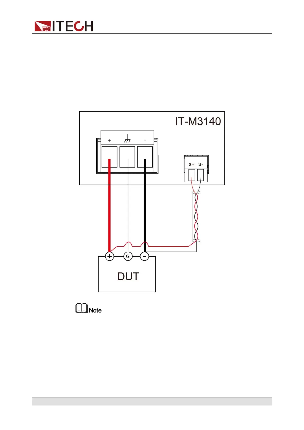
The connection diagram and steps of remote sensing are as follows.
To ensure the stability of the system, use armored twisted-pair cables be-
tween the remote sense terminals and the equipment under test.
1. Remove the output terminal cover.
2. Loosen the screws of the output terminals and connect the red and black
test cables to the output terminals, and connect the ground terminal cor-
rectly. Re-tighten the screws.
When maximum current that one test cable can withstand fails to meet the
current rated current, use multiple pieces of red and black test cables. For
example, the maximum current is 1,200 A, then 4 pieces of 360 A red and
black cables are required.
Copyright © Itech Electronic Co., Ltd.
23

 Loading...