Inspection and Installation
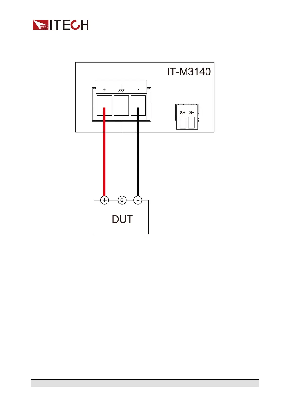
Local Measurement
The connection diagram and steps of local sensing are as follows.
1. Remove the output terminal cover.
2. Loosen the screws of the output terminals and connect the red and black
test cables to the output terminals, and connect the ground terminal cor-
rectly. Re-tighten the screws.
When maximum current that one test cable can withstand fails to meet the
current rated current, use multiple pieces of red and black test cables. For
example, the maximum current is 1,200 A, then 4 pieces of 360 A red and
black cables are required.
3. Thread the test cables through the output terminals cover and install the
cover.
4. Connect the other end of the red and black cables to the DUT. The positive
and negative poles must be properly connected and fastened when wiring.
Remote Sensing
When the DUT consumes large current or the wires are too long, there is a volt-
age drop on the wires between the DUT and output terminal of the power sup-
ply. To maximize measurement accuracy, you can use remote sense wire
Copyright © Itech Electronic Co., Ltd.
22

 Loading...