Quick Start
Copyright © ITECH Electronic Co., Ltd. 18
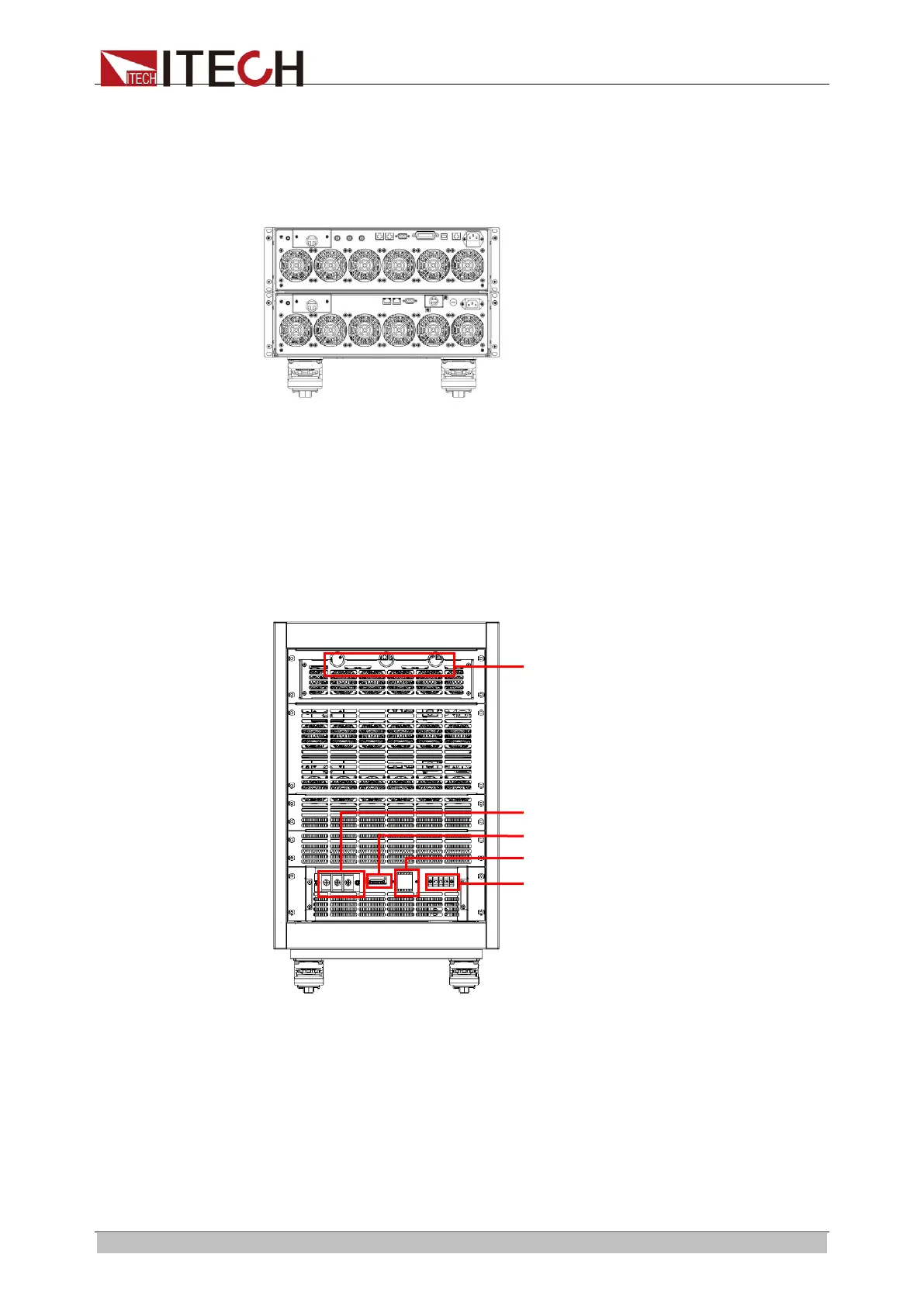
⚫ The rear panel of IT8616/IT8617 side plate structure is shown in the next
figure.IT8616 electronic load consists of two IT8615 and IT8617 electronic
load consists of three IT8615. Take the example of IT8616, the rear panel
of the instrument above is the same as that of IT8615. Except the system
bus terminals and AC power input sockets, the instruments below have no
communication interfaces. The rear panel of IT8616 is shown as below:
⚫ The rear panel of IT8616(15U cabinet)/IT8617 (15U cabinet: one master
and two slaves) is shown in the next figure.
Take the example of IT8617, before connecting the communication
terminals, you need to take apart the rear panel which covers the
communication terminals by using a screwdriver. The communication
terminals of 15U cabinet are the same as those of the side plate structure.
Before connecting the load input terminals and AC power input terminals,
you also need to take apart the rear panel which covers them by using a
screwdriver. The figure below shows the rear panel.
1. Communication interface threading hole
2. Load input terminals
3. Remote measurement terminals
4. Power master switch
5. AC power input terminals
ООО "Техэнком" Контрольно-измерительные приборы и оборудование www.tehencom.com

 Loading...