Basic Operations
Copyright © ITECH Electronic Co., Ltd. 32
3.13 Remote Measurement Function
In the loading mode, if high current is required or the wire is long, a great
voltage drop will occur on the connecting wire between the test object and load
terminal. To ensure the measurement accuracy, a remote measurement
terminal is set on the rear panel of the electronic load to be used for measuring
the output terminal voltage of the test object.
When the load is used for measuring battery discharge in actual applications,
the voltage drop of the wire will lead to voltage inconsistency of both ends and
inconsistency of the cutoff voltage of load and the actual voltage of battery,
resulting in inaccurate measurement.
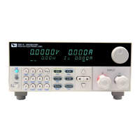
Take the example of IT8615 electronic load, the schematic diagram of remote
measurement terminals is as follows. The actual terminals are subject to the
real instrument.
Vs+/Vs-: remote measurement terminal. When the remote measurement
function is used, Vs+ and Vs- are connected to the test object.
V+/V-: input terminal.
Use remote sense:
⚫ Remote measurement function is always applied to connection of test lines
for Model IT8615/IT8615L/ IT8616 (side plate structure)/ IT8617 (side plate
structure and three masters in 15U cabinet). Refer to 1.4 Connecting Test
Lines for the wiring.
⚫ The operations for Model IT8616 (15U cabinet)/IT8617 (one master and
two slaves in 15U cabinet)/IT8624/IT8625/IT8626/IT8627/IT8628 are as
follows:
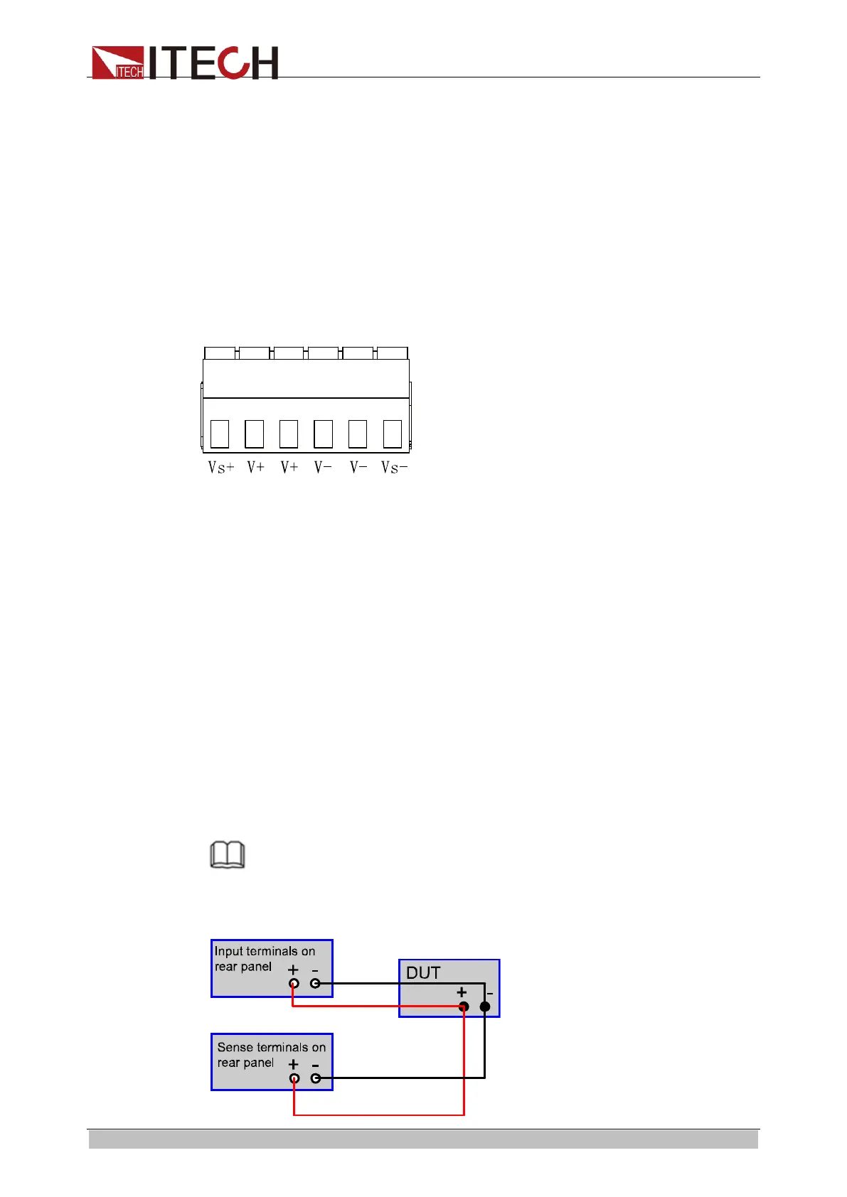
1. Disconnect the wires/short clips between V+ and Vs+, V- and Vs-.
2. Connect the Vs+ to the DUT’s L terminal, and connect the Vs- to the
DUT’s N terminal.
3. Connect the drive wires from the rear panel terminals to the tested
equipment.
NOTE
In order to ensure the stability of the system, using armored twisted pair cable between
the remote sense terminals and DUT.
The schematic diagram of remote sense measurement is shown as follow.
ООО "Техэнком" Контрольно-измерительные приборы и оборудование www.tehencom.com

 Loading...